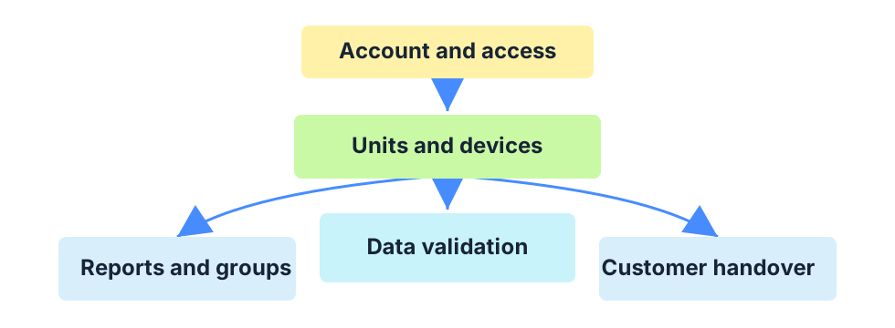
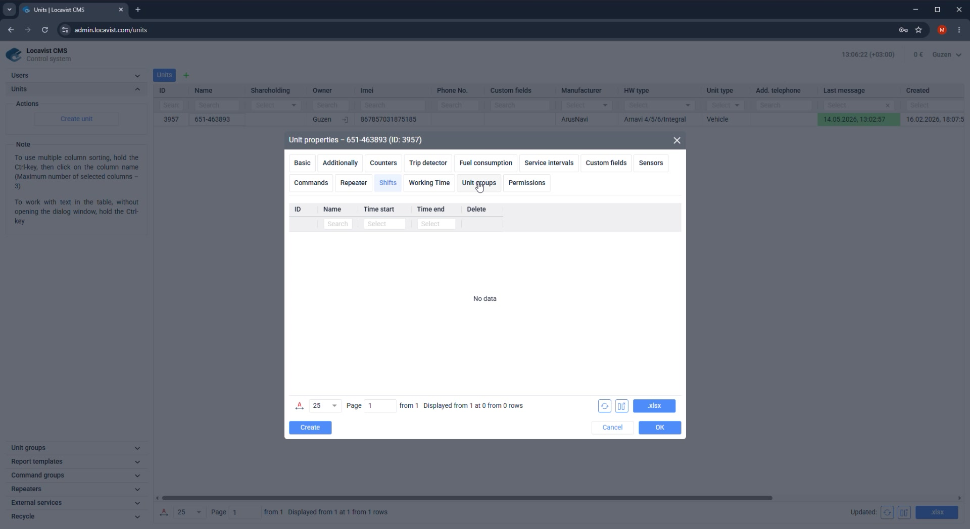
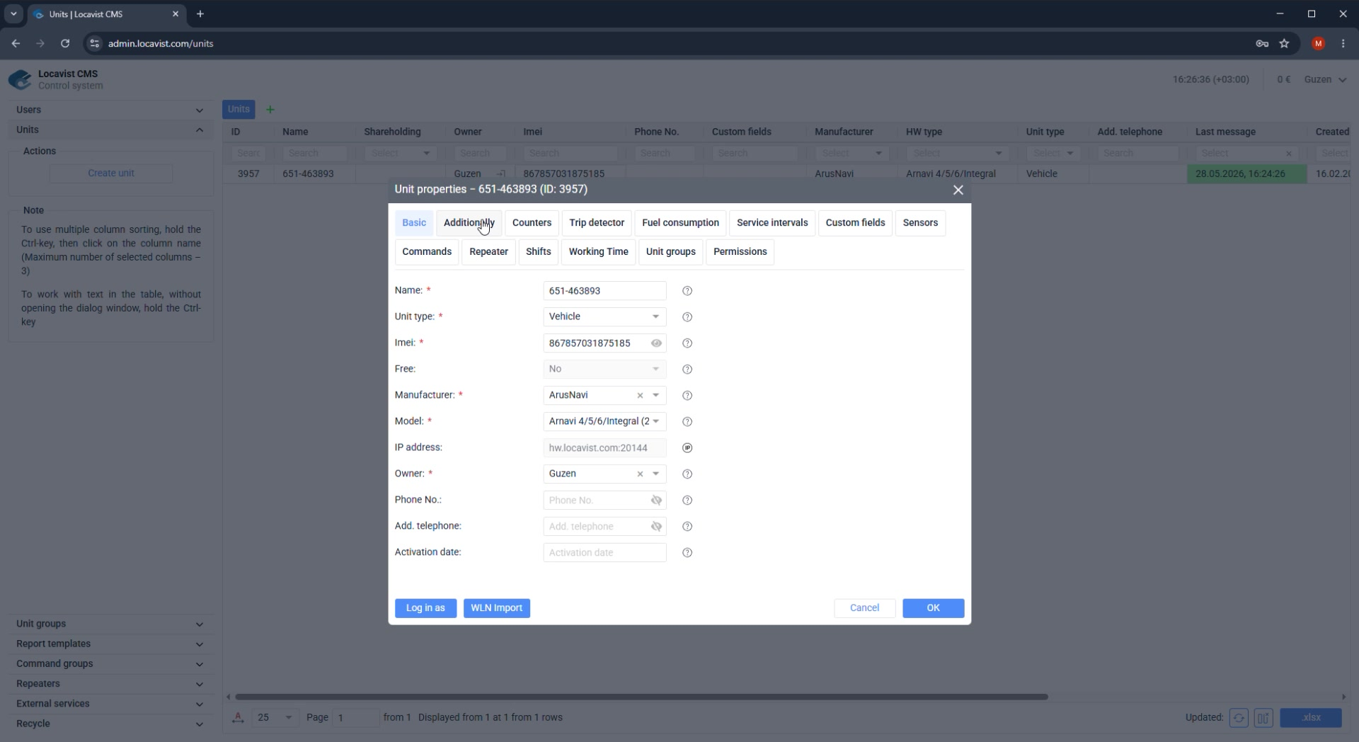
A practical administrator guide for creating users, configuring billing, adding units, checking reports, and preparing the account for customer handover.
Purpose
Use the guide as an implementation route, not as a gallery of CMS screens. Each topic explains the decision behind the setting, where the setting is checked later, and what must be clear before handover.
Where it affects the account
The order matters because early account choices influence unit ownership, visible modules, billing counters, reports, and the customer's first support questions.
How to read the page
Read the explanation first, then apply the numbered steps, then use the final check as the condition for moving to the next topic.
Screenshot 01. Locavist CMS User Guide
Setup steps
1
Use this guide as the standard workflow for the first customer setup.
2
Configure the account first, then add units, check reports, and prepare handover notes.
3
If an Interface update dialog appears on login, update before starting or choose Update later only after saving current work.
Administrator note
Follow the pages in order when preparing a new customer account. Each page explains what to configure, what to verify, and why the step matters.
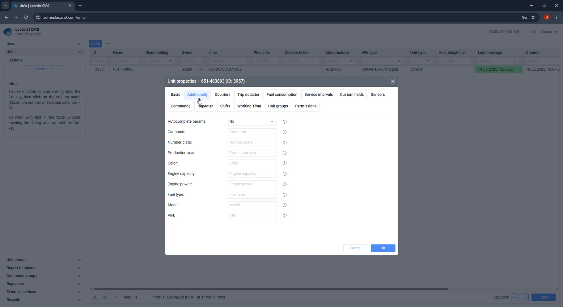
Result
The guide gives administrators a repeatable checklist and reduces support questions after handover.
Check before continuing
Do not skip verification steps when the account looks ready at first glance.
02Start
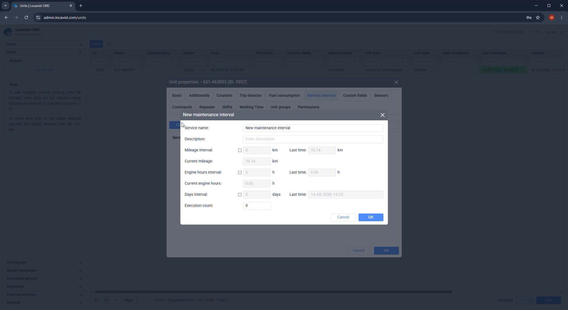
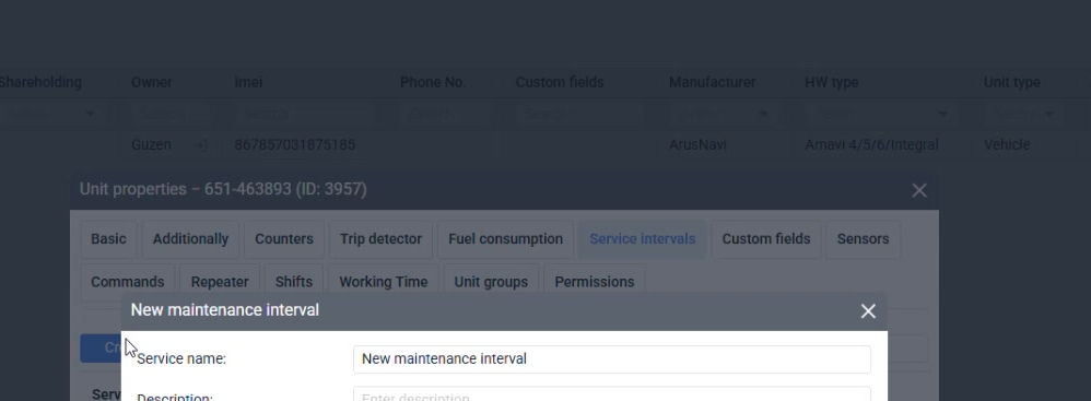
How to use this guide
Each page describes one setup area, the required actions, and the checks to complete before moving to the next area.
Purpose
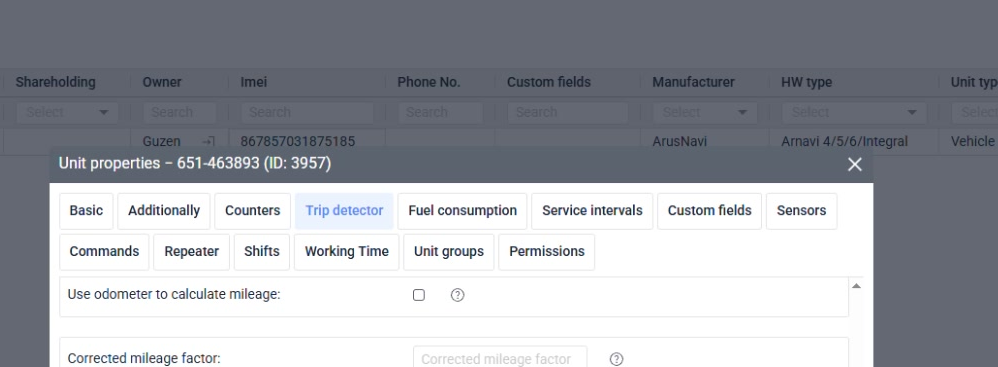
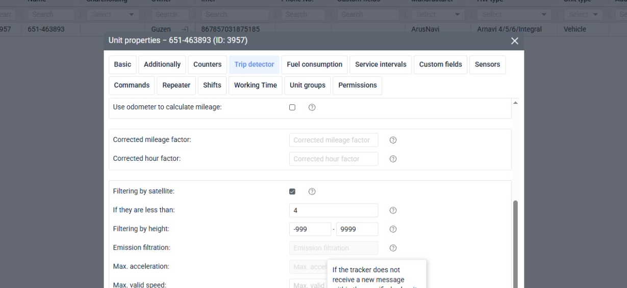
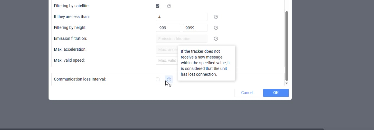
This section explains the operating logic of the guide before an administrator starts changing a live customer account.
Where it affects the account
A consistent route helps every installer prepare accounts in the same order and makes later support work easier to audit.
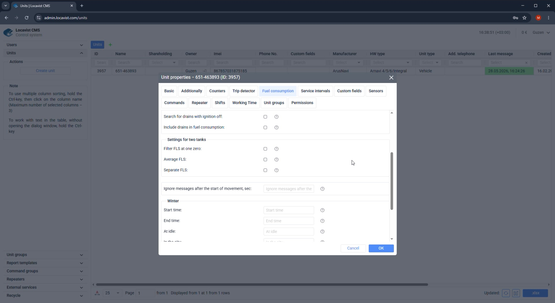
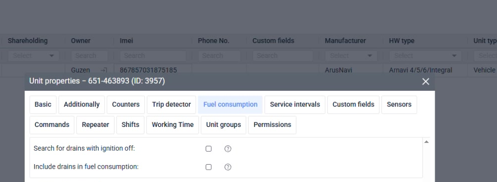
How to read the page
Use the section labels and screenshots as orientation, but rely on the notes and checks to decide whether the setup is actually complete.
Screenshot 02. How to use this guide
Setup steps
1
Start with the section label: CMS, Units, Trip, Fuel, Sensors, Groups, Reports, or Handover.
2
Follow the action list in order.
3
Use the checks at the end of the page to confirm the setup is complete.
Focus detail. How to use this guide
Administrator note
Screenshots are intentionally mixed: some are full screens for orientation; some are cropped so the relevant control is large enough to read.
Result
Screenshots are scaled to show the control being described.
Check before continuing
Do not skip the small checks. They catch most early account mistakes.
03CMS
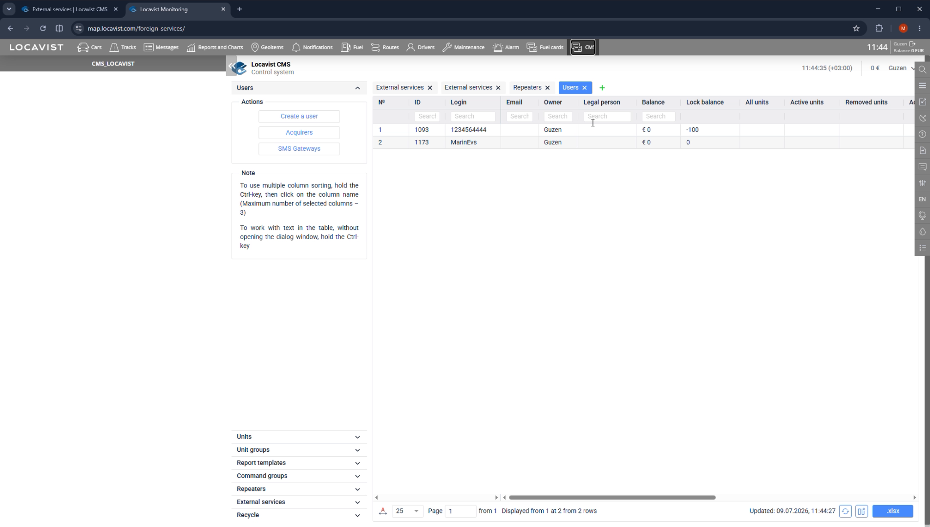
User menu overview
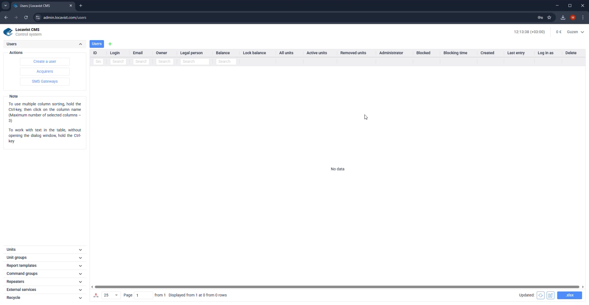
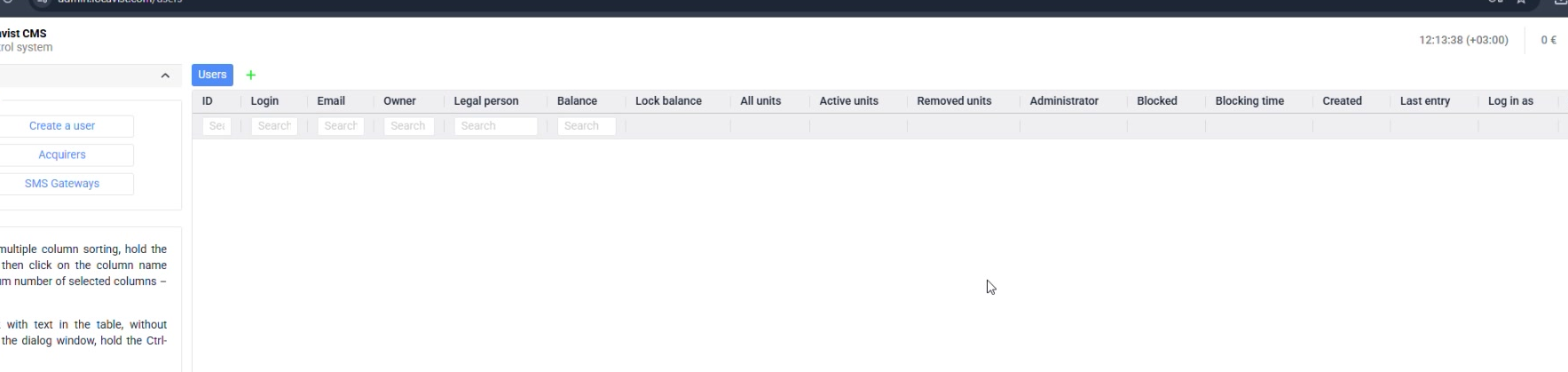
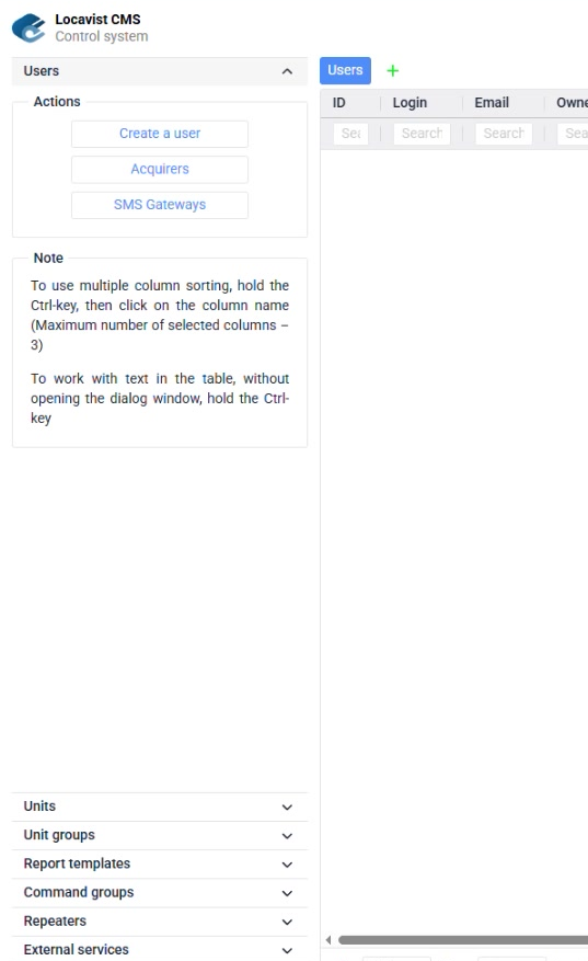
The Users list shows account access, owner, balance, limits, login state, and recent activity.
Purpose
CMS settings define who owns the account, who can administer it, and which identity data support and billing will trust later.
Where it affects the account
Wrong ownership, role, timezone, or contact data can make a technically working account hard to support, bill, or transfer.
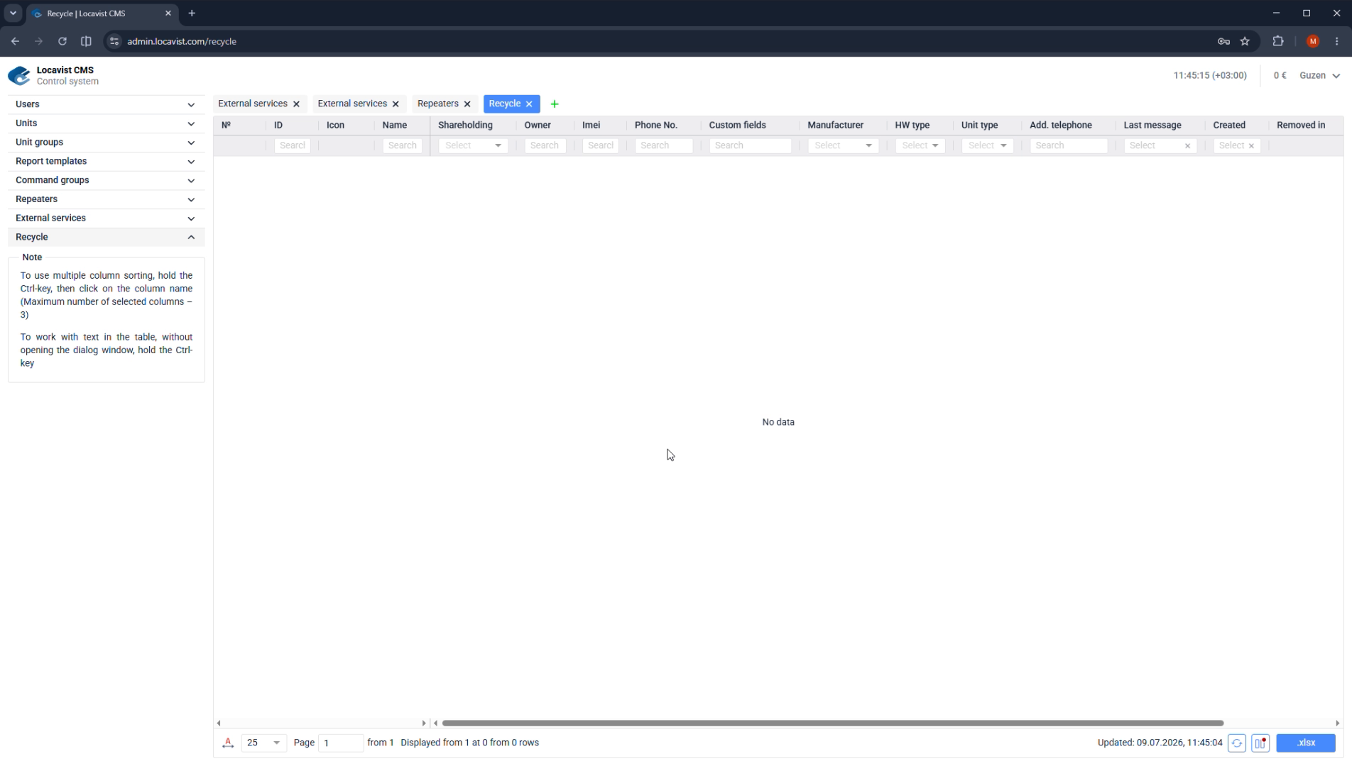
How to read the screen
Before changing values, identify the user, owner, role, and visible action area; after saving, reopen or log in as the user when the change affects access.
Screenshot 03. User menu overview
Setup steps
1
Open the Users area in CMS; most admin sessions land here after login.
2
Review the columns: Login, Email, Owner, Legal person, Balance, Lock balance, All units, Active units, Removed units, Administrator, Blocked, Blocking time, Created, Last entry, Log in as, and Delete.
3
Use the per-column Search fields and Reset all columns before editing when the list grows.
Focus detail. User menu overview
Administrator note
Treat this screen as the account dashboard. It also shows action buttons such as Create a user, Acquirers, and SMS Gateways in the left Actions panel.
Result
Reviewing these columns first helps prevent editing the wrong account.
Check before continuing
The table can look empty if filters are active. Clear filters before assuming data is missing; hold Ctrl when sorting multiple columns or editing table text inline.
04CMS
Create a clean user record
Create customer users with names, ownership, and contact data that another administrator can verify later.
Purpose
CMS settings define who owns the account, who can administer it, and which identity data support and billing will trust later.
Where it affects the account
Wrong ownership, role, timezone, or contact data can make a technically working account hard to support, bill, or transfer.
How to read the screen
Before changing values, identify the user, owner, role, and visible action area; after saving, reopen or log in as the user when the change affects access.
Screenshot 04. Create a clean user record
Setup steps
1
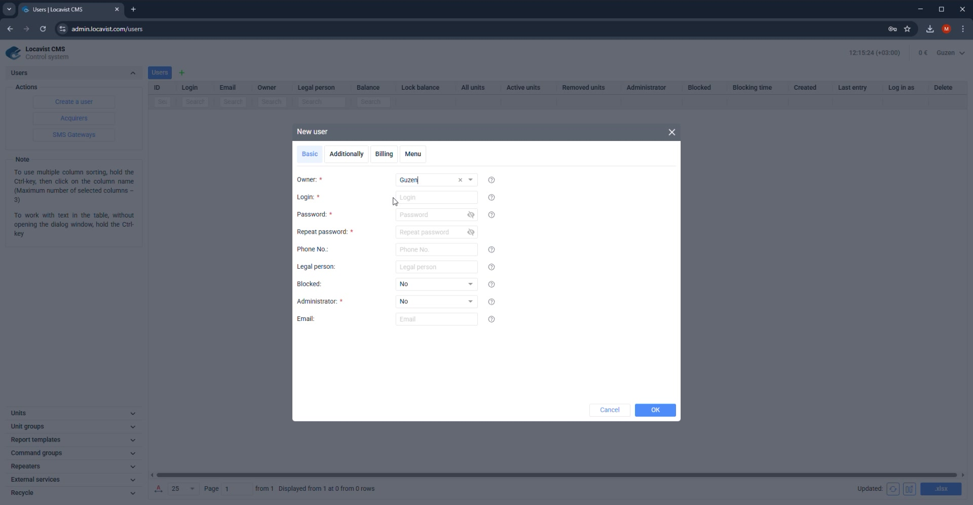
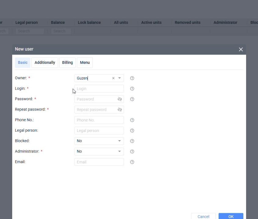
Click Create a user.
2
Fill login, email, legal person, and ownership fields consistently.
3
Set contact fields only with data that support can trust.
4
Save, then reopen the user to confirm persisted values.
Focus detail. Create a clean user record
Administrator note
Use names and legal labels that match the commercial contract or support records. Avoid shorthand that only one installer understands.
Result
Clean identity data makes billing, support, and audits easier.
Check before continuing
Never create production customers with temporary credentials that will be forgotten.
05CMS
Roles and administrator rights
Administrator access determines whether the user can open the CMS admin panel.
Purpose
CMS settings define who owns the account, who can administer it, and which identity data support and billing will trust later.
Where it affects the account
Wrong ownership, role, timezone, or contact data can make a technically working account hard to support, bill, or transfer.
How to read the screen
Before changing values, identify the user, owner, role, and visible action area; after saving, reopen or log in as the user when the change affects access.
Screenshot 05. Roles and administrator rights
Setup steps
1
Decide whether the person is an operator, customer admin, reseller admin, or CMS admin.
2
Enable administrator rights only when CMS access is required.
3
Record who approved elevated access.
4
Test login from the intended user role.
Focus detail. Roles and administrator rights
Administrator note
Most customer users should work in monitoring, not in CMS. CMS rights change the risk profile of the account.
Result
Least privilege keeps onboarding safer.
Check before continuing
Do not use administrator rights as a quick workaround for missing permissions.
06Billing
Choose the billing model
Billing decides what the platform charges for and how object count is interpreted.
Purpose
Billing pages translate the commercial agreement into Locavist account behavior: what is charged, when it is charged, and when service should stop.
Where it affects the account
These settings affect balance history, active object counters, blocking behavior, finance reconciliation, and customer explanations.
How to read the screen
Do not treat billing fields as defaults to accept quickly; compare every period, threshold, price, and limit against the customer agreement.
Screenshot 06. Choose the billing model
Setup steps
1
Open the Billing tab.
2
Choose billing by active units, all units, or the contract-specific model.
3
Confirm the meaning of removed or inactive units.
4
Save the model before setting prices and limits.
Focus detail. Choose the billing model
Administrator note
Active-unit and all-unit billing lead to different operational behavior. Make the decision explicit.
Result
The billing model is a commercial setting, not a purely technical one.
Check before continuing
Changing the model after launch can create reconciliation problems.
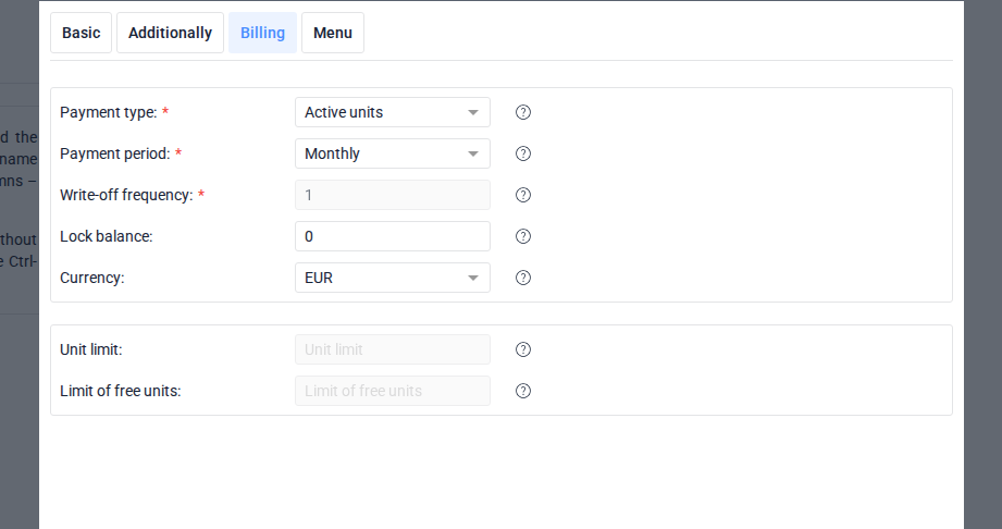
07Billing
Daily and monthly periods
The billing period controls when balance is debited and how quickly blocks can happen.
Purpose
Billing pages translate the commercial agreement into Locavist account behavior: what is charged, when it is charged, and when service should stop.
Where it affects the account
These settings affect balance history, active object counters, blocking behavior, finance reconciliation, and customer explanations.
How to read the screen
Do not treat billing fields as defaults to accept quickly; compare every period, threshold, price, and limit against the customer agreement.
Screenshot 07. Daily and monthly periods
Setup steps
1
Choose daily billing when usage should be charged every day.
2
Choose monthly billing when balance is debited on the monthly cycle.
3
Confirm the first billing date with the customer agreement.
4
Document special exceptions.
Focus detail. Daily and monthly periods
Administrator note
Billing period affects support questions when a customer asks why balance changed today.
Result
Predictable billing reduces finance disputes.
Check before continuing
Do not leave a default period without checking the contract.
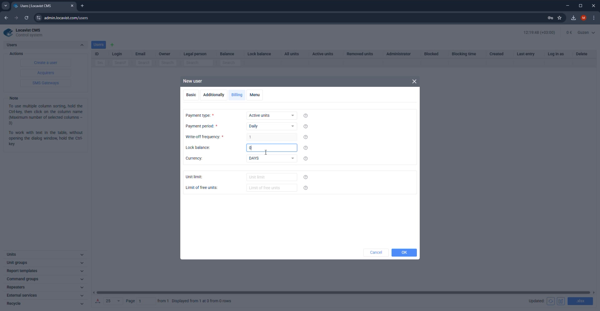
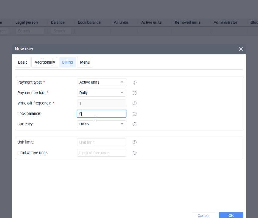
08Billing
Balance and lock balance
Balance shows the account state; lock balance defines when the account should be blocked.
Purpose
Billing pages translate the commercial agreement into Locavist account behavior: what is charged, when it is charged, and when service should stop.
Where it affects the account
These settings affect balance history, active object counters, blocking behavior, finance reconciliation, and customer explanations.
How to read the screen
Do not treat billing fields as defaults to accept quickly; compare every period, threshold, price, and limit against the customer agreement.
Screenshot 08. Balance and lock balance
Setup steps
1
Review the current Balance value in the Users list.
2
Set Lock balance if service must stop below a threshold.
3
Review blocked status after saving.
4
Top up balance through Transactions or API when needed.
Focus detail. Balance and lock balance
Administrator note
Lock balance is a customer experience setting: too strict and service stops unexpectedly; too loose and debt grows.
Result
The threshold makes billing behavior transparent.
Check before continuing
Never use blocking to solve a permission or configuration issue.
09Billing
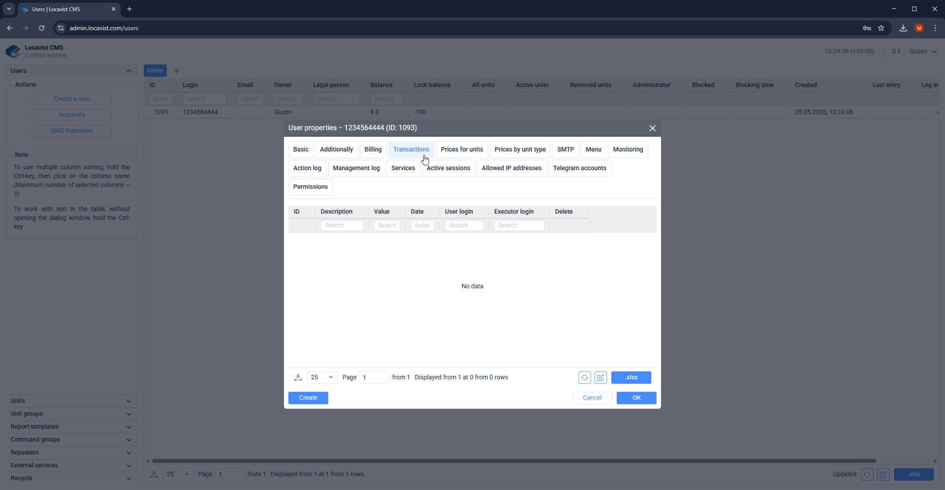
Transactions and balance top-ups
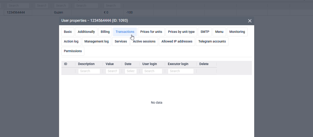
The Transactions tab shows billing deductions and administrator balance top-ups for the user account.
Purpose
Billing pages translate the commercial agreement into Locavist account behavior: what is charged, when it is charged, and when service should stop.
Where it affects the account
These settings affect balance history, active object counters, blocking behavior, finance reconciliation, and customer explanations.
How to read the screen
Do not treat billing fields as defaults to accept quickly; compare every period, threshold, price, and limit against the customer agreement.
Screenshot 09. Transactions and balance top-ups
Setup steps
1
Open the Transactions tab when checking why the user balance changed.
2
Treat negative transaction rows as system billing deductions.
3
Use administrator balance top-ups when money is added manually or through API integration.
4
Check Description, Price, Period, Date, and user balance after any correction.
Focus detail. Transactions and balance top-ups
Administrator note
This tab is the account ledger: billing creates deductions, while administrator or API operations add funds.
Result
Transactions give finance and support a traceable history of charges and balance corrections.
Check before continuing
Balance corrections must be intentional and traceable.
10Access
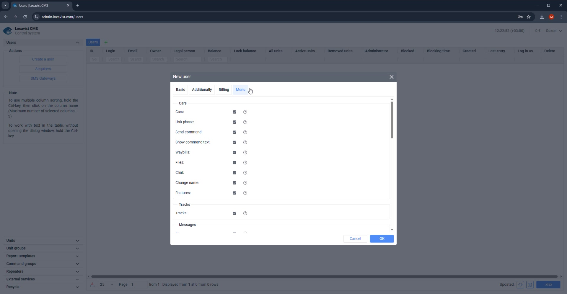
Menu visibility
Menu visibility shapes what the customer sees during onboarding.
Purpose
Access pages shape the customer's everyday workspace and the evidence administrators use when something changes later.
Where it affects the account
Menu visibility, monitoring options, logs, services, sessions, and IP restrictions decide what the user can see, do, and verify.
How to read the screen
After a CMS-side change, confirm the result from the customer role because visibility and permissions can look correct in CMS but fail in Monitoring.
Screenshot 10. Menu visibility
Setup steps
1
Open the Menu tab.
2
Hide modules outside the current contract or training scope.
3
Keep core monitoring paths visible.
4
Write down intentionally hidden modules.
Focus detail. Menu visibility
Administrator note
A smaller menu helps the customer learn faster and creates fewer support questions.
Result
A controlled menu reduces training time and support questions.
Check before continuing
Hidden modules can look like missing features unless documented.
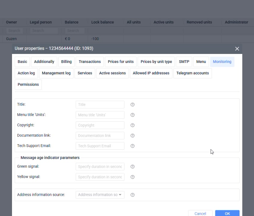
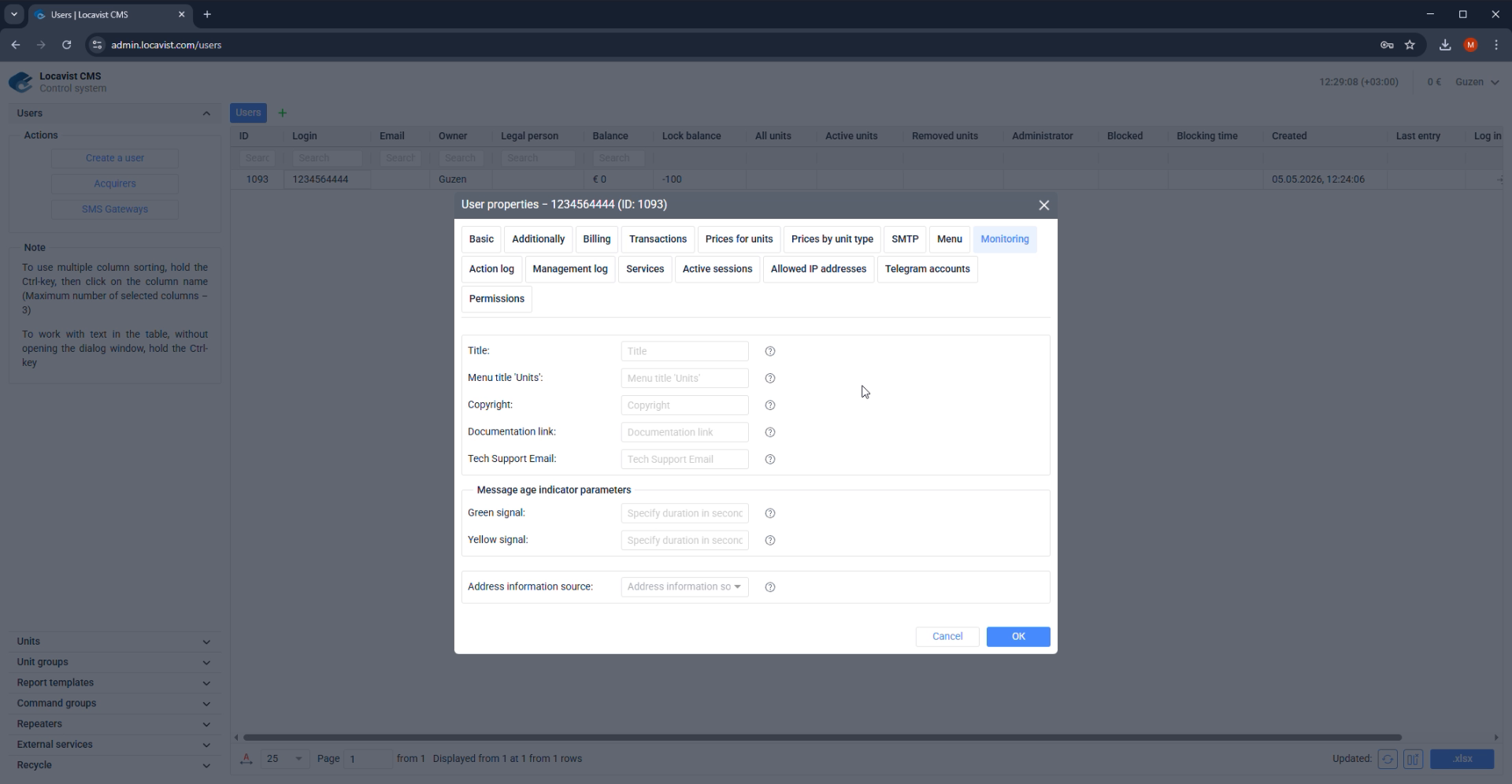
11Access
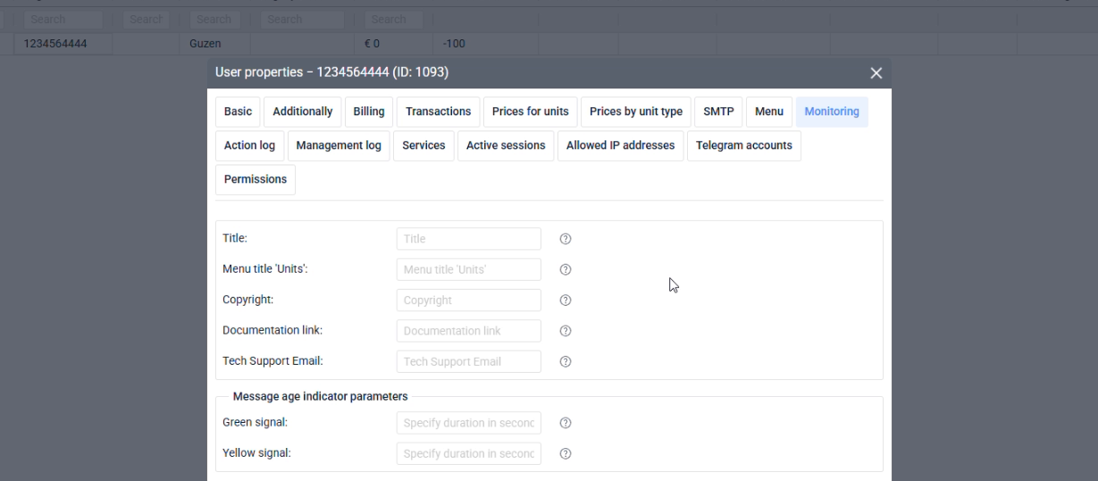
Monitoring customization
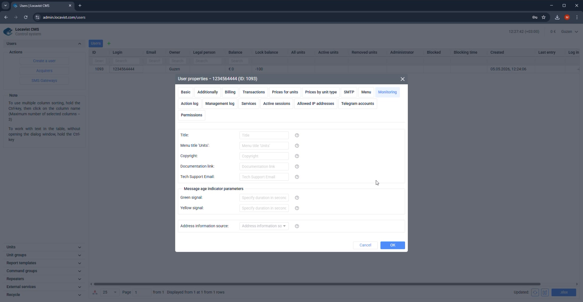
Monitoring options decide which operational tools the user can reach after login.
Purpose
Access pages shape the customer's everyday workspace and the evidence administrators use when something changes later.
Where it affects the account
Menu visibility, monitoring options, logs, services, sessions, and IP restrictions decide what the user can see, do, and verify.
How to read the screen
After a CMS-side change, confirm the result from the customer role because visibility and permissions can look correct in CMS but fail in Monitoring.
Screenshot 11. Monitoring customization
Setup steps
1
Open the Monitoring tab.
2
Enable only the features required for the customer role.
3
Check report, object, and map-related options.
4
Test with a real login after saving.
Focus detail. Monitoring customization
Administrator note
The monitoring screen is the customer's daily workspace; keep it focused.
Result
Role-specific visibility makes the interface easier to use.
Check before continuing
Do not assume CMS settings are correct until the monitoring side is checked.
12Access
Action and management logs
The log tabs show user actions and administrator changes made to the user account.
Purpose
Access pages shape the customer's everyday workspace and the evidence administrators use when something changes later.
Where it affects the account
Menu visibility, monitoring options, logs, services, sessions, and IP restrictions decide what the user can see, do, and verify.
How to read the screen
After a CMS-side change, confirm the result from the customer role because visibility and permissions can look correct in CMS but fail in Monitoring.
Screenshot 12. Action and management logs
Setup steps
1
Open Action log to check actions performed by the user.
2
Open Management log to check actions performed on the user account.
3
Use log entries when investigating changed objects, access, or account settings.
4
Record only the relevant date, action, and actor in support notes.
Focus detail. Action and management logs
Administrator note
Action log and Management log answer different questions: what the user did, and what was done to the user account.
Result
Logs provide evidence for support investigations.
Check before continuing
Do not send internal logs to customers without removing sensitive details.
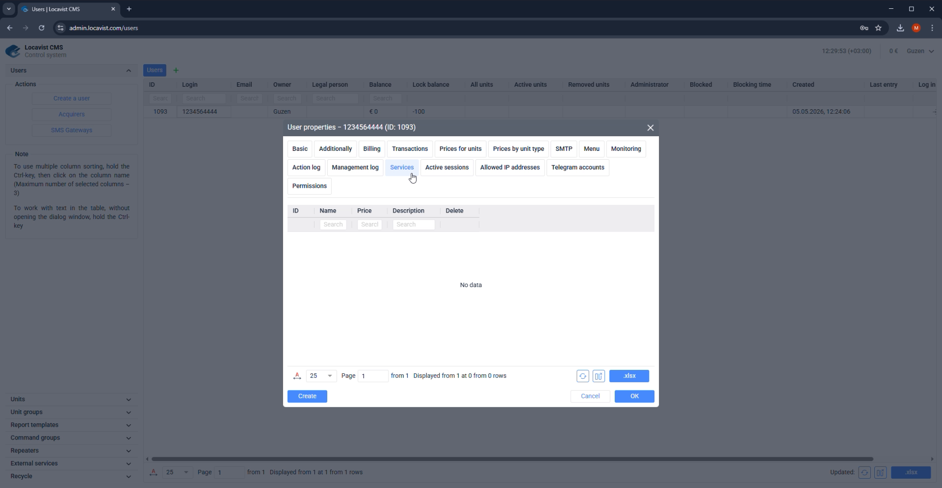
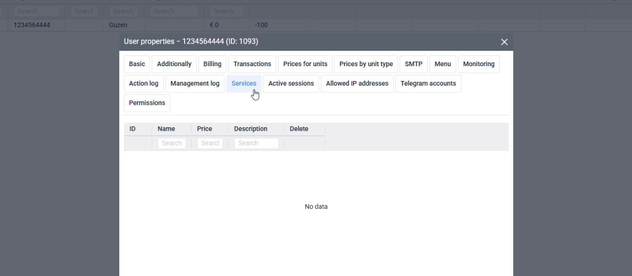
13Access
Service charges
The Services tab is used for fixed recurring charges that are not tied to unit count.
Purpose
Access pages shape the customer's everyday workspace and the evidence administrators use when something changes later.
Where it affects the account
Menu visibility, monitoring options, logs, services, sessions, and IP restrictions decide what the user can see, do, and verify.
How to read the screen
After a CMS-side change, confirm the result from the customer role because visibility and permissions can look correct in CMS but fail in Monitoring.
Screenshot 13. Service charges
Setup steps
1
Open Services when a customer has an additional paid service or customization.
2
Create a service row with a clear Description.
3
Set the Price and Period that match the commercial agreement.
4
Check the next billing cycle if the charge should repeat automatically.
Focus detail. Service charges
Administrator note
Use Services for agreed fixed fees, for example monthly customization or support charges.
Result
Service rows make non-unit charges visible in the account.
Check before continuing
Do not use service charges to replace object billing or manual balance top-ups.
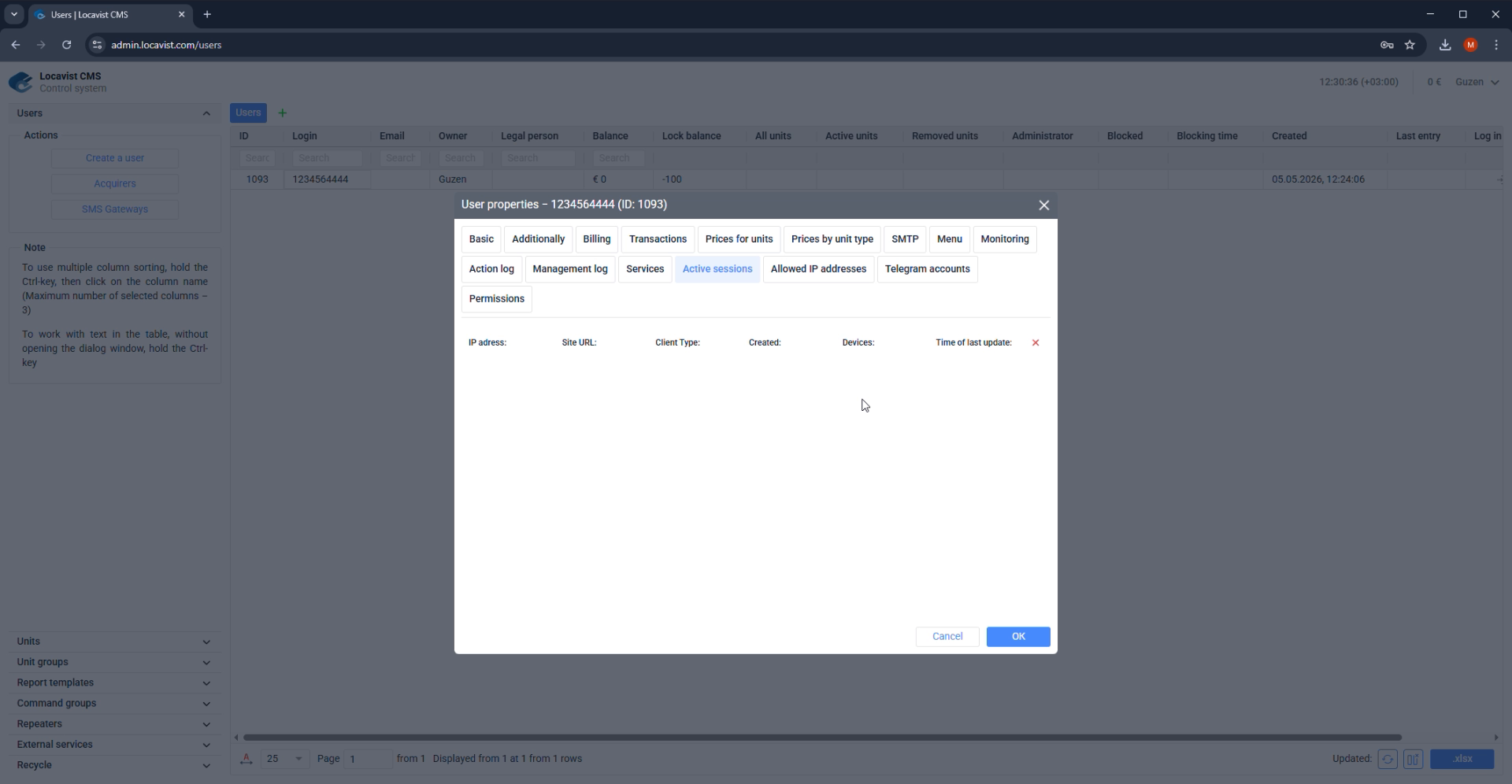
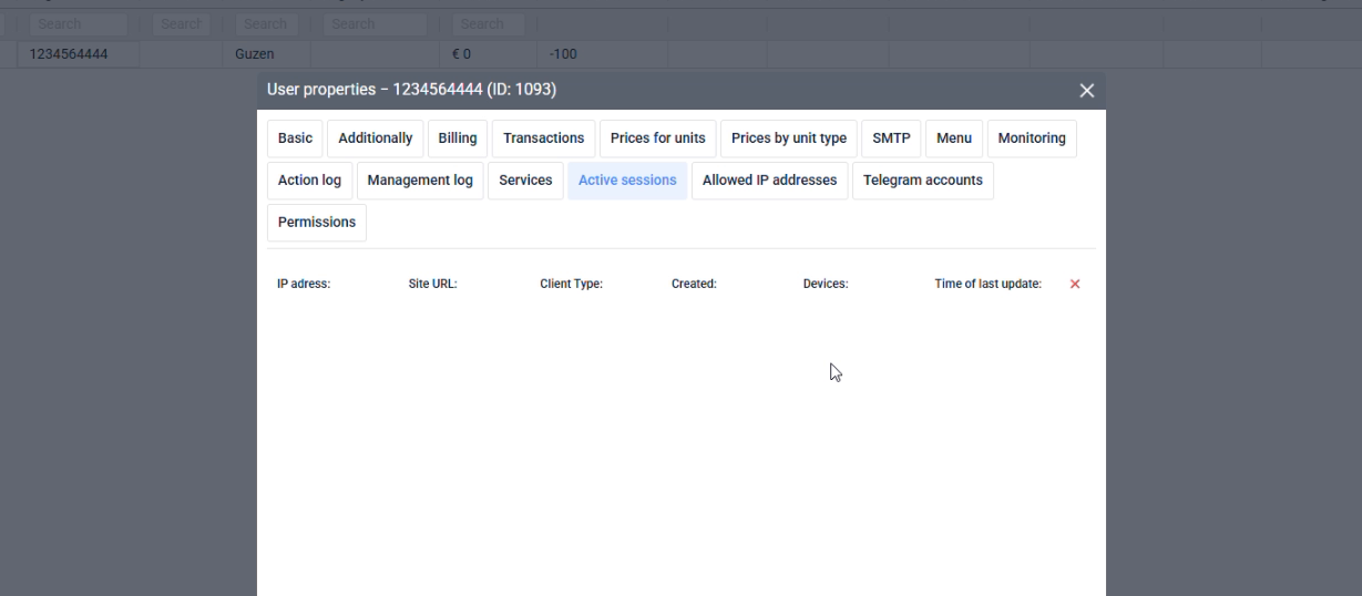
14Access
Active sessions
The Active sessions tab shows current connections for the selected user account.
Purpose
Access pages shape the customer's everyday workspace and the evidence administrators use when something changes later.
Where it affects the account
Menu visibility, monitoring options, logs, services, sessions, and IP restrictions decide what the user can see, do, and verify.
How to read the screen
After a CMS-side change, confirm the result from the customer role because visibility and permissions can look correct in CMS but fail in Monitoring.
Screenshot 14. Active sessions
Setup steps
1
Open Active sessions when investigating active logins or access complaints.
2
Review Date, Client type, Location, Duration, and Time of last update.
3
Use Delete Everything only when all active sessions must be closed.
4
Ask the user to sign in again after sessions are cleared.
Focus detail. Active sessions
Administrator note
Active Sessions is an operational troubleshooting screen, not a permission editor.
Result
Session checks show whether the account is currently in use.
Check before continuing
Closing all sessions interrupts every current login for that user.
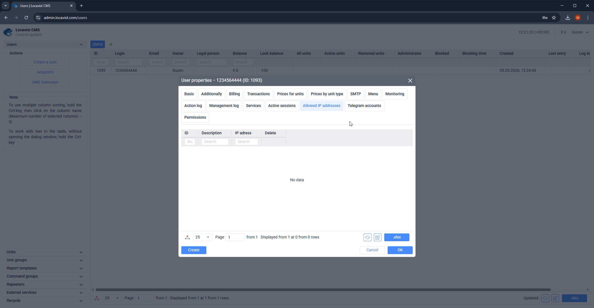
15Access
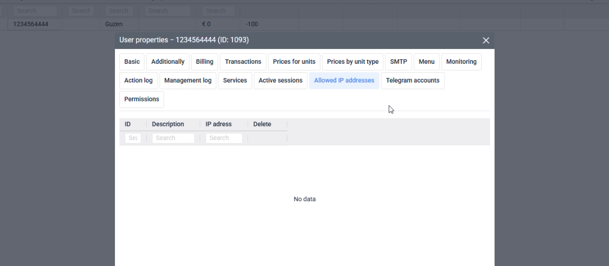
Allowed IP addresses
Allowed IP addresses restrict where a user can sign in from when static IP control is required.
Purpose
Access pages shape the customer's everyday workspace and the evidence administrators use when something changes later.
Where it affects the account
Menu visibility, monitoring options, logs, services, sessions, and IP restrictions decide what the user can see, do, and verify.
How to read the screen
After a CMS-side change, confirm the result from the customer role because visibility and permissions can look correct in CMS but fail in Monitoring.
Screenshot 15. Allowed IP addresses
Setup steps
1
Open Allowed IP addresses only for accounts that require static IP access control.
2
Add the exact IP addresses agreed with the customer.
3
Do not enter ranges when the interface requires specific addresses.
4
Test access from the allowed location before handover.
Focus detail. Allowed IP addresses
Administrator note
Use this tab only when the customer has fixed network addresses and understands the access restriction.
Result
IP restrictions reduce unauthorized access for accounts that use fixed networks.
Check before continuing
Wrong IP settings can block legitimate users.
16Units
Object list orientation
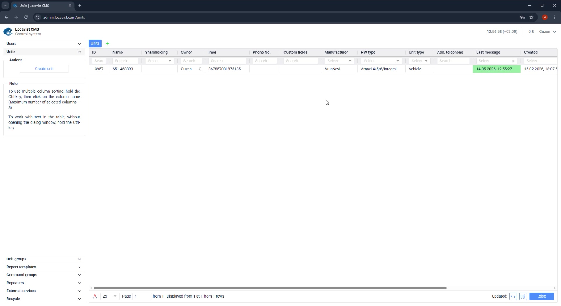
The Units list is the main table for monitored vehicles, machines, and other tracked assets.
Purpose
Unit setup turns a vehicle or asset into a monitored object with a reliable identity, owner, tracker model, and operational metadata.
Where it affects the account
Unit fields become map labels, report filters, permission targets, maintenance references, and support clues when telemetry is missing.
How to read the screen
Separate descriptive fields from telemetry-critical fields: name and type help people recognize the unit, while device ID and model decide whether data arrives.
Screenshot 16. Object list orientation
Setup steps
1
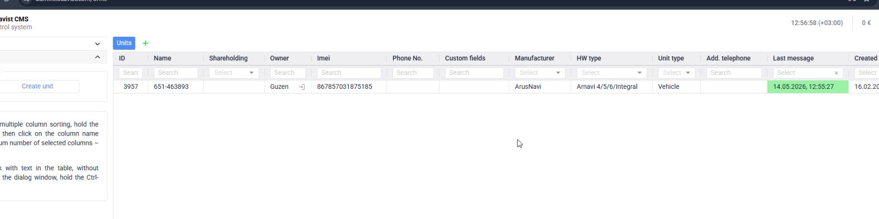
Open Units and review Icon, Name, Shareholding, Owner, Imei, Phone No., Custom fields, Manufacturer, HW type, Unit type, Last message, Available to users, Send command, Copy, and Delete.
2
Use search before editing.
3
Check last message to confirm the tracker is alive.
4
Open the object only after confirming you selected the right row.
Focus detail. Object list orientation
Administrator note
The unit list tells you whether the setup is only created or already receiving data.
Result
The last message column is a quick health check.
Check before continuing
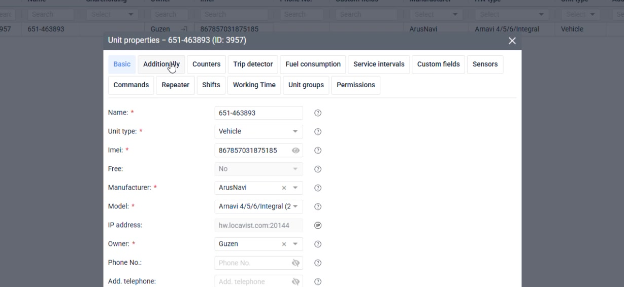
If a button such as Create unit does not open a dialog, first check the current role, session state, and whether an interface update dialog is blocking the page.
17Units
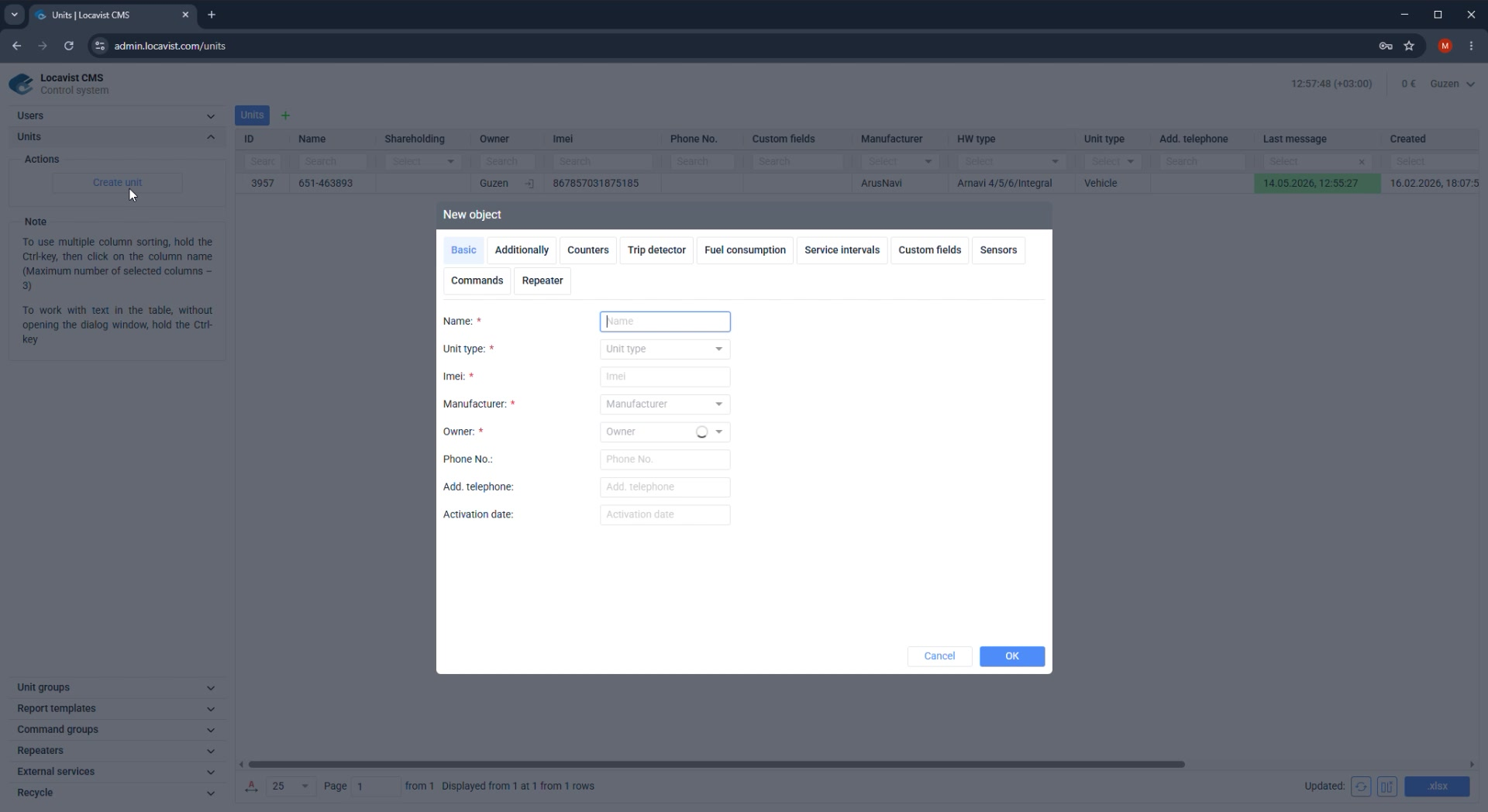
Create a unit
Create the monitored object before configuring its device, counters, trip rules, and sensors.
Purpose
Unit setup turns a vehicle or asset into a monitored object with a reliable identity, owner, tracker model, and operational metadata.
Where it affects the account
Unit fields become map labels, report filters, permission targets, maintenance references, and support clues when telemetry is missing.
How to read the screen
Separate descriptive fields from telemetry-critical fields: name and type help people recognize the unit, while device ID and model decide whether data arrives.
Screenshot 17. Create a unit
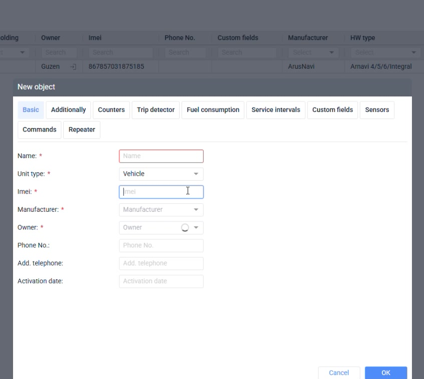
Setup steps
1
Click Create unit.
2
Enter a production name, not a temporary label.
3
Choose Unit type, then enter Imei.
4
Choose Manufacturer; after that, choose the required Model that appears below it.
5
Choose Owner and save the object, then reopen it for module settings.
Focus detail. Create a unit
Administrator note
The live form shows required fields in this order: Name, Unit type, Imei, Manufacturer, Model, and Owner. Model appears only after Manufacturer is selected.
Result
A clear naming convention scales better than memory.
Check before continuing
Avoid using the customer's internal slang unless it is documented.
18Units
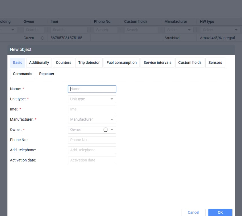
Basic identity fields
Name, unit type, manufacturer, model, owner, and phone fields make the object recognizable and supportable.
Purpose
Unit setup turns a vehicle or asset into a monitored object with a reliable identity, owner, tracker model, and operational metadata.
Where it affects the account
Unit fields become map labels, report filters, permission targets, maintenance references, and support clues when telemetry is missing.
How to read the screen
Separate descriptive fields from telemetry-critical fields: name and type help people recognize the unit, while device ID and model decide whether data arrives.
Screenshot 18. Basic identity fields
Setup steps
1
Fill Name and Unit type first.
2
Select Manufacturer and then the required Model from the filtered list.
3
Set Owner; for a single-account setup this may simply be the current login.
4
Add phone fields only when the data is reliable.
5
Keep optional fields empty rather than wrong.
Focus detail. Basic identity fields
Administrator note
Basic identity fields become filters, report labels, and support clues.
Result
Good metadata lowers future search time.
Check before continuing
Wrong optional fields are worse than absent ones.
19Units
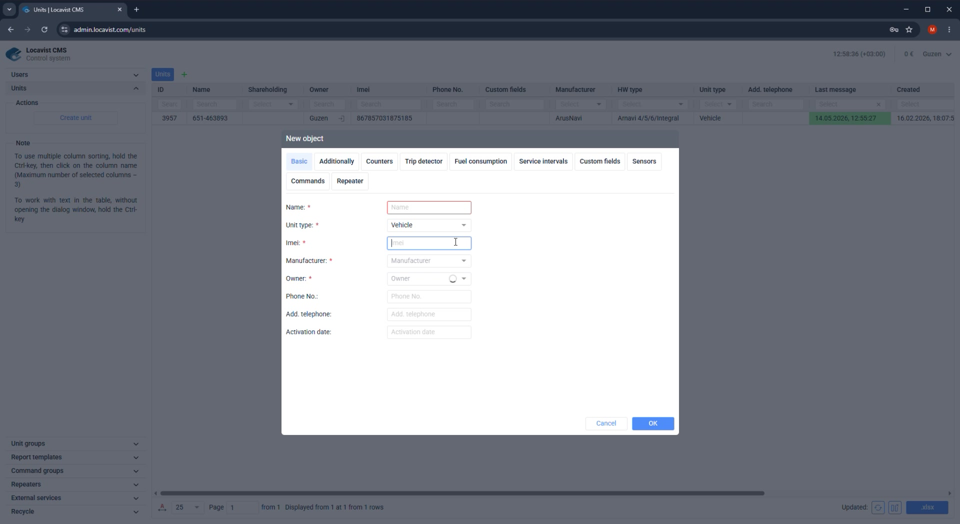
Device ID and model
The unique ID or IMEI connects the CMS unit to the tracker data stream.
Purpose
Unit setup turns a vehicle or asset into a monitored object with a reliable identity, owner, tracker model, and operational metadata.
Where it affects the account
Unit fields become map labels, report filters, permission targets, maintenance references, and support clues when telemetry is missing.
How to read the screen
Separate descriptive fields from telemetry-critical fields: name and type help people recognize the unit, while device ID and model decide whether data arrives.
Screenshot 19. Device ID and model
Setup steps
1
Copy the ID from a trusted source.
2
Choose the correct hardware model.
3
Check protocol-specific requirements if data does not arrive.
4
Confirm live data in monitoring.
Focus detail. Device ID and model
Administrator note
A unit with a wrong ID looks configured but remains silent.
Result
This is the most common one-character failure point.
Check before continuing
Do not troubleshoot reports before confirming device data arrives.
20Units
Counters and mileage
Counters translate raw movement data into operational totals.
Purpose
Unit setup turns a vehicle or asset into a monitored object with a reliable identity, owner, tracker model, and operational metadata.
Where it affects the account
Unit fields become map labels, report filters, permission targets, maintenance references, and support clues when telemetry is missing.
How to read the screen
Separate descriptive fields from telemetry-critical fields: name and type help people recognize the unit, while device ID and model decide whether data arrives.
Screenshot 20. Counters and mileage
Setup steps
1
Review odometer and mileage counters.
2
Choose the source that matches tracker quality.
3
Check whether counters should start from existing vehicle values.
4
Verify the first report after real movement.
Focus detail. Counters and mileage
Administrator note
Counters often become billing, maintenance, or compliance inputs.
Result
Accurate counters reduce manual corrections.
Check before continuing
Do not mix GPS-derived mileage and hardware odometer logic without a reason.
21Units
Engine hours and ignition
Engine-hour logic depends on a reliable ignition or equivalent signal.
Purpose
Unit setup turns a vehicle or asset into a monitored object with a reliable identity, owner, tracker model, and operational metadata.
Where it affects the account
Unit fields become map labels, report filters, permission targets, maintenance references, and support clues when telemetry is missing.
How to read the screen
Separate descriptive fields from telemetry-critical fields: name and type help people recognize the unit, while device ID and model decide whether data arrives.
Screenshot 21. Engine hours and ignition
Setup steps
1
Confirm the ignition sensor exists.
2
Choose when engine time should count.
3
Check idling scenarios with the customer.
4
Validate on a period where ignition changes occurred.
Focus detail. Engine hours and ignition
Administrator note
Engine hours are important for equipment where distance is less meaningful than working time.
Result
Ignition quality controls report quality.
Check before continuing
Do not promise engine-hour reports before validating the signal.
22Units
Maintenance and custom fields
Maintenance and custom fields store context that is not part of live telemetry.
Purpose
Unit setup turns a vehicle or asset into a monitored object with a reliable identity, owner, tracker model, and operational metadata.
Where it affects the account
Unit fields become map labels, report filters, permission targets, maintenance references, and support clues when telemetry is missing.
How to read the screen
Separate descriptive fields from telemetry-critical fields: name and type help people recognize the unit, while device ID and model decide whether data arrives.
Screenshot 22. Maintenance and custom fields
Setup steps
1
Add maintenance rules only when someone will use them.
2
Use custom fields for stable business identifiers.
3
Avoid duplicating information already present in unit name or owner.
4
Review fields during handover.
Focus detail. Maintenance and custom fields
Administrator note
These fields help support and operations understand the asset without external spreadsheets.
Result
Useful metadata should be structured.
Check before continuing
Free-text fields become messy if no naming rule exists.
23Commands
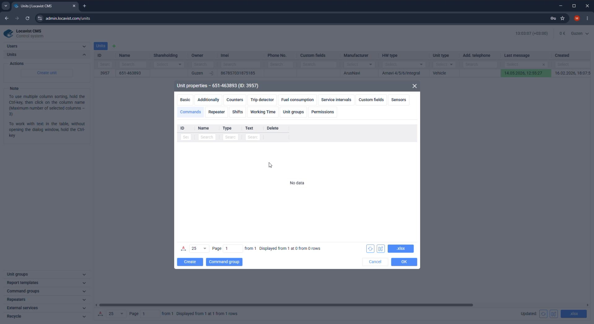
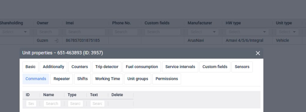
Commands and repeaters
Commands and repeaters are powerful controls, so they should be configured deliberately.
Purpose
Use the guide as an implementation route, not as a gallery of CMS screens. Each topic explains the decision behind the setting, where the setting is checked later, and what must be clear before handover.
Where it affects the account
The order matters because early account choices influence unit ownership, visible modules, billing counters, reports, and the customer's first support questions.
How to read the page
Read the explanation first, then apply the numbered steps, then use the final check as the condition for moving to the next topic.
Screenshot 23. Commands and repeaters
Setup steps
1
Open the Commands and Repeater tabs.
2
Enable only commands that match the device and customer role.
3
Check repeater targets before activating data forwarding.
4
Document any remote-control capability.
Focus detail. Commands and repeaters
Administrator note
Remote commands and repeaters can affect real-world assets and external systems.
Result
Strong controls need clear ownership.
Check before continuing
Never expose a command just because the device supports it.
24Permissions
Unit groups and permissions
Object groups are the clean way to scale access from one unit to many.
Purpose
Use the guide as an implementation route, not as a gallery of CMS screens. Each topic explains the decision behind the setting, where the setting is checked later, and what must be clear before handover.
Where it affects the account
The order matters because early account choices influence unit ownership, visible modules, billing counters, reports, and the customer's first support questions.
How to read the page
Read the explanation first, then apply the numbered steps, then use the final check as the condition for moving to the next topic.
Screenshot 24. Unit groups and permissions
Setup steps
1
Create groups that match the customer's departments, branches, or fleets.
2
Assign each unit to the correct group.
3
Grant users access through groups where possible.
4
Review group membership after adding new objects.
Focus detail. Unit groups and permissions
Administrator note
Groups prevent permission drift as the customer grows.
Result
Good group design saves future cleanup.
Check before continuing
Do not use one giant group for customers with separated responsibilities.
25Trip
Trip detector fundamentals
Trip detector settings decide when the system considers movement to be a trip.
Purpose
Trip detector settings decide how raw messages become trips, stops, mileage, working time, and later report rows.
Where it affects the account
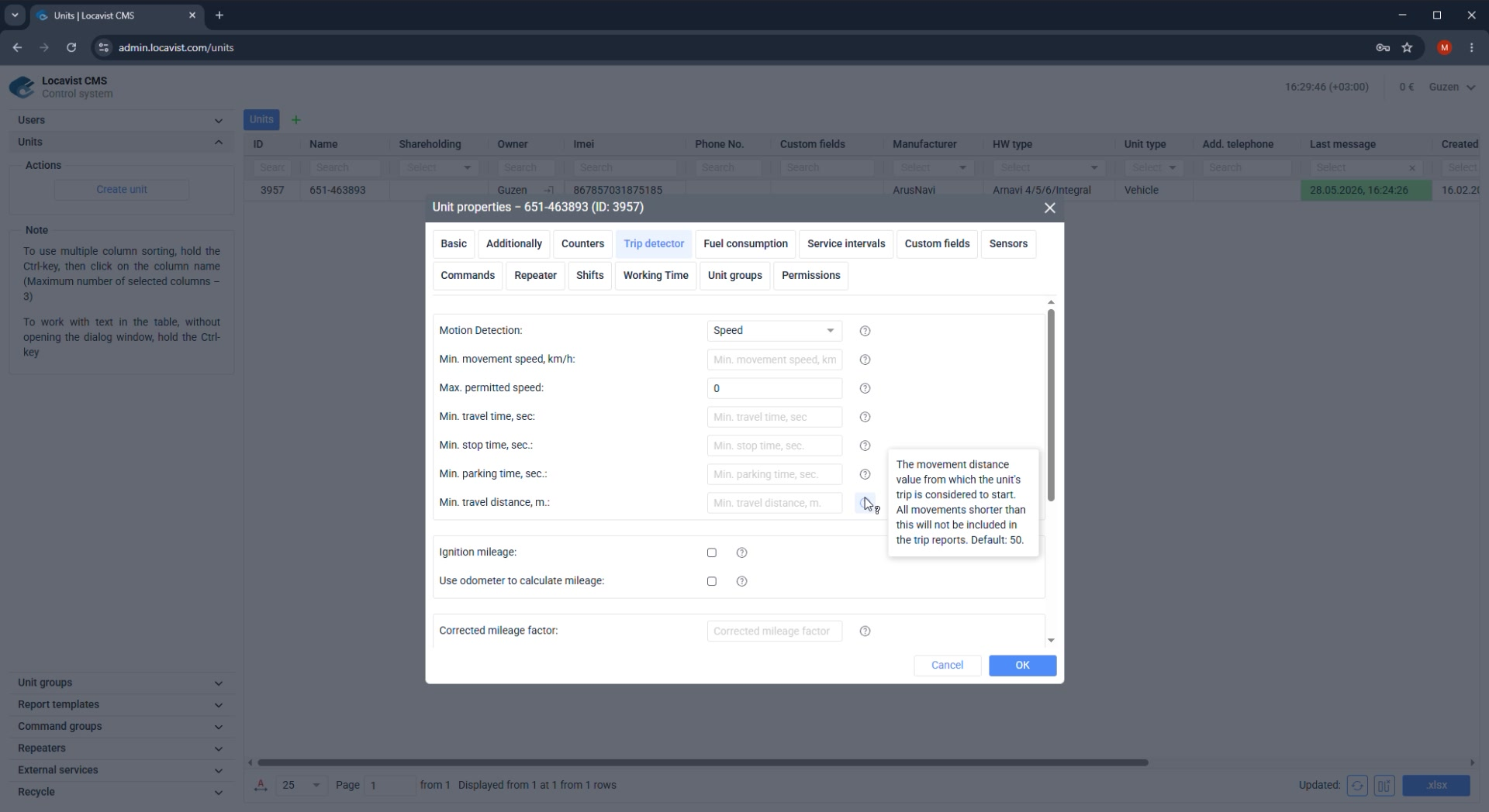
A small threshold mistake can create false trips, hide real movement, distort mileage, or make the first customer report look unreliable.
How to read the screen
Choose logic that matches the tracker and vehicle type, then validate it with real messages instead of assuming one global rule fits every unit.
Screenshot 25. Trip detector fundamentals
Setup steps
1
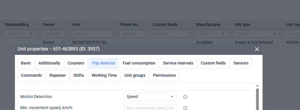
Choose a movement source: GPS speed, ignition, or odometer.
2
Keep the first setup conservative.
3
Review stop and movement thresholds.
4
Validate using real trips, not only stationary data.
Focus detail. Trip detector fundamentals
Administrator note
Trip logic affects routes, reports, work time, and fuel interpretation.
Result
Trips are a foundation setting.
Check before continuing
Do not overfit thresholds before enough data exists.
26Trip
Movement source selection
The movement source should match what the tracker sends reliably.
Purpose
Trip detector settings decide how raw messages become trips, stops, mileage, working time, and later report rows.
Where it affects the account
A small threshold mistake can create false trips, hide real movement, distort mileage, or make the first customer report look unreliable.
How to read the screen
Choose logic that matches the tracker and vehicle type, then validate it with real messages instead of assuming one global rule fits every unit.
Screenshot 26. Movement source selection
Setup steps
1
Use GPS speed when position data is stable.
2
Use ignition when engine state is the business definition of movement.
3
Use odometer when distance changes are the cleanest signal.
4
Explain the selected logic in handover notes.
Focus detail. Movement source selection
Administrator note
Different vehicle types can need different movement logic.
Result
The source should reflect operations, not only defaults.
Check before continuing
One setting rarely fits every unit type.
27Trip
Thresholds and filters
Thresholds define which movement events are included in trips and reports.
Purpose
Trip detector settings decide how raw messages become trips, stops, mileage, working time, and later report rows.
Where it affects the account
A small threshold mistake can create false trips, hide real movement, distort mileage, or make the first customer report look unreliable.
How to read the screen
Choose logic that matches the tracker and vehicle type, then validate it with real messages instead of assuming one global rule fits every unit.
Screenshot 27. Thresholds and filters
Setup steps
1
Review minimum trip duration or distance.
2
Set stop and parking logic carefully.
3
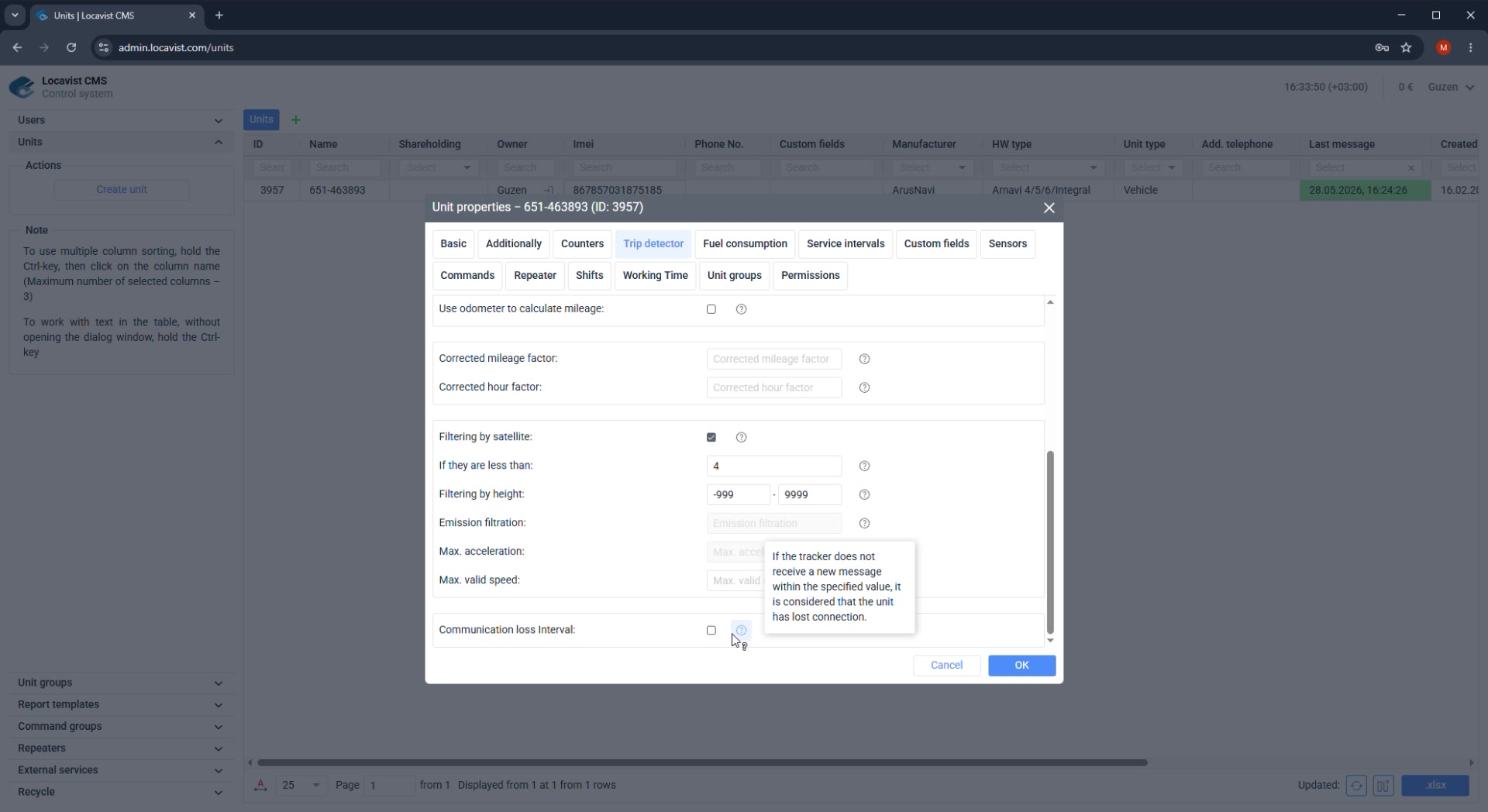
Use filters to remove false jumps.
4
Compare with map playback after the first trips.
Focus detail. Thresholds and filters
Administrator note
Incorrect thresholds can create false trips in reports.
Result
Filtering should remove false events without hiding real trips.
Check before continuing
Too much filtering can hide real short trips.
28Fuel
Fuel consumption overview
Fuel settings define consumption logic, refueling, drains, and filtering.
Purpose
Fuel settings explain how Locavist should turn sensor readings into consumption, refueling, drain, and tank-level conclusions.
Where it affects the account
Fuel logic feeds reports and alerts that customers often treat as financial evidence, so bad calibration quickly becomes a business dispute.
How to read the screen
Start from the sensor source and tank model, then tune thresholds and filters only after checking real readings over a known route or day.
Screenshot 28. Fuel consumption overview
Setup steps
1
Open Fuel consumption.
2
Review minimum refueling and drain volumes.
3
Check maximum consumption interval logic.
4
Keep initial values simple until real fuel data is reviewed.
Focus detail. Fuel consumption overview
Administrator note
Fuel reports are valuable but very sensitive to bad sensor data.
Result
Start with reliable basics.
Check before continuing
Do not treat fuel settings as a substitute for sensor calibration.
29Fuel
Refueling and drain thresholds
Minimum volumes define when a fuel level change is recorded as a refueling or drain event.
Purpose
Fuel settings explain how Locavist should turn sensor readings into consumption, refueling, drain, and tank-level conclusions.
Where it affects the account
Fuel logic feeds reports and alerts that customers often treat as financial evidence, so bad calibration quickly becomes a business dispute.
How to read the screen
Start from the sensor source and tank model, then tune thresholds and filters only after checking real readings over a known route or day.
Screenshot 29. Refueling and drain thresholds
Setup steps
1
Set minimum refueling volume according to the vehicle tank.
2
Set minimum drain volume according to normal sensor fluctuation.
3
Review event grouping interval.
4
Compare events with known refueling records.
Focus detail. Refueling and drain thresholds
Administrator note
Wrong thresholds create either missing refuels or false drain alerts.
Result
Thresholds should match physical reality.
Check before continuing
Small vehicles and heavy equipment should not share blind defaults.
30Fuel
Fuel filtering
Filtering reduces GPS and sensor noise, but it does not replace hardware diagnostics.
Purpose
Fuel settings explain how Locavist should turn sensor readings into consumption, refueling, drain, and tank-level conclusions.
Where it affects the account
Fuel logic feeds reports and alerts that customers often treat as financial evidence, so bad calibration quickly becomes a business dispute.
How to read the screen
Start from the sensor source and tank model, then tune thresholds and filters only after checking real readings over a known route or day.
Screenshot 30. Fuel filtering
Setup steps
1
Start with the recommended moderate filtering level.
2
Increase only when real data shows unstable readings.
3
Check whether the sensor itself needs service.
4
Document changes for future support.
Focus detail. Fuel filtering
Administrator note
Good filtering improves reports; excessive filtering hides problems.
Result
Filtering should be adjusted only after reviewing real data.
Check before continuing
If level 3 is not enough, investigate the physical sensor or tracker data.
31Fuel
Multiple tanks and summary fuel
Locavist can combine several fuel level sensors into a summary value.
Purpose
Fuel settings explain how Locavist should turn sensor readings into consumption, refueling, drain, and tank-level conclusions.
Where it affects the account
Fuel logic feeds reports and alerts that customers often treat as financial evidence, so bad calibration quickly becomes a business dispute.
How to read the screen
Start from the sensor source and tank model, then tune thresholds and filters only after checking real readings over a known route or day.
Screenshot 31. Multiple tanks and summary fuel
Setup steps
1
Create or import each fuel level sensor.
2
Check how the system should behave if one sensor stops sending values.
3
Choose average, separate, or combined behavior according to the customer need.
4
Validate tank totals with real data.
Focus detail. Multiple tanks and summary fuel
Administrator note
Multi-tank setups are easy to misread unless behavior is explicit.
Result
Summary fuel must be predictable.
Check before continuing
Do not combine tanks when the customer needs separate tank reporting.
32Sensors
Sensor strategy
Sensors convert raw device parameters into values customers can understand.
Purpose
Sensor configuration gives meaning to raw tracker parameters and decides which values are visible, valid, converted, and reportable.
Where it affects the account
Sensors connect telemetry to monitoring cards, charts, fuel calculations, temperature traces, custom columns, and automation rules.
How to read the screen
For each sensor, confirm the parameter source, type, validation rule, conversion table, and whether the customer should see the value in daily work.
Screenshot 32. Sensor strategy
Setup steps
1
List required outcomes first: ignition, fuel, doors, temperature, PTO, or custom signals.
2
Import from a similar unit when possible.
3
Create manually when the tracker setup is unique.
4
Name sensors for operators, not engineers only.
Focus detail. Sensor strategy
Administrator note
Sensor planning prevents a messy list of half-used parameters.
Result
Good sensors make reports readable.
Check before continuing
Do not create every available parameter as a customer-facing sensor.
33Sensors
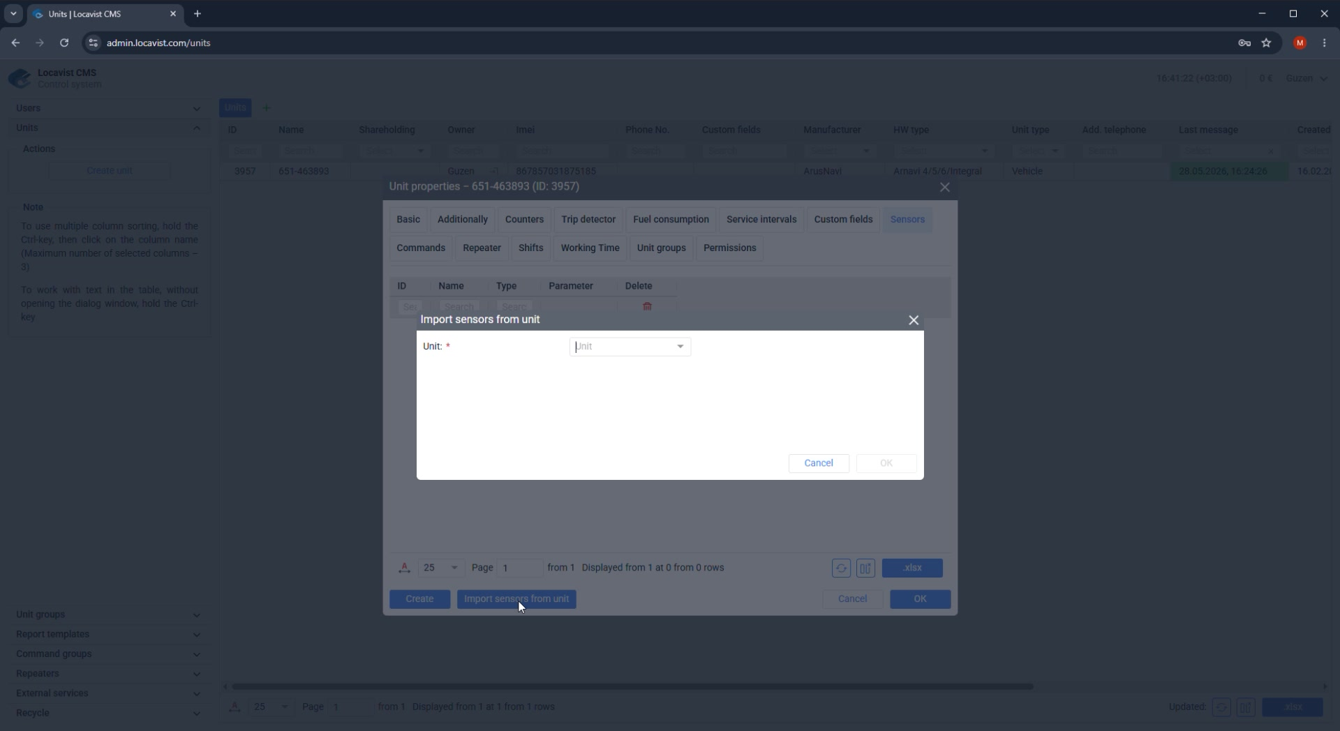
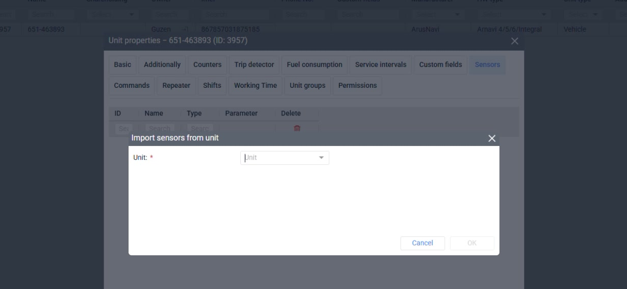
Import sensors from a unit
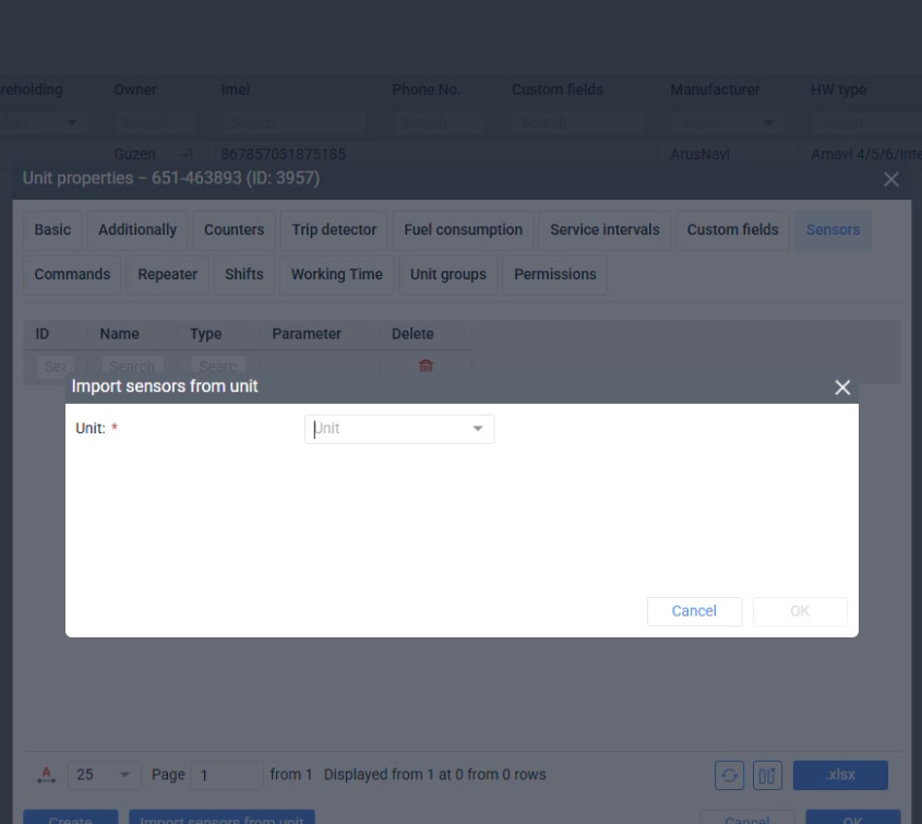
Importing sensors saves time when several units share the same hardware and wiring.
Purpose
Sensor configuration gives meaning to raw tracker parameters and decides which values are visible, valid, converted, and reportable.
Where it affects the account
Sensors connect telemetry to monitoring cards, charts, fuel calculations, temperature traces, custom columns, and automation rules.
How to read the screen
For each sensor, confirm the parameter source, type, validation rule, conversion table, and whether the customer should see the value in daily work.
Screenshot 33. Import sensors from a unit
Setup steps
1
Click Import Sensors from Unit.
2
Choose a known-good source unit.
3
Import, then review every sensor name and parameter.
4
Validate after the first live messages arrive.
Focus detail. Import sensors from a unit
Administrator note
Import is fast, but it also copies old assumptions.
Result
Reuse only from clean templates.
Check before continuing
Do not import from a unit that was tuned for a different tracker model.
34Sensors
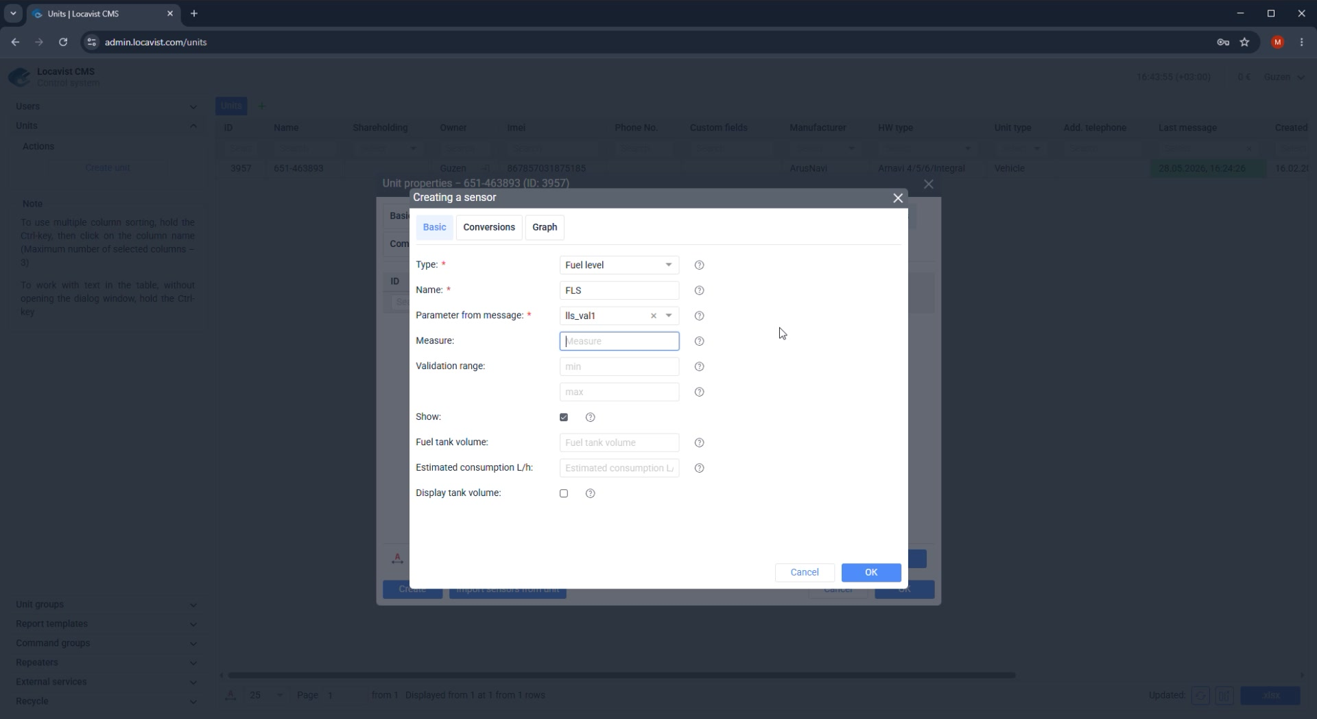
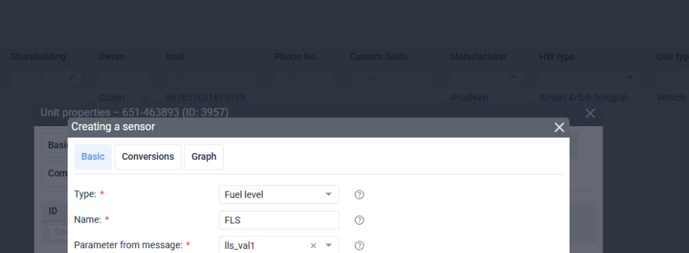
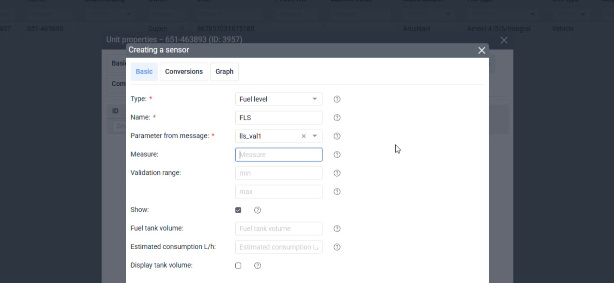
Create a sensor manually
Manual creation starts with the sensor type, then the parameter and display rules.
Purpose
Sensor configuration gives meaning to raw tracker parameters and decides which values are visible, valid, converted, and reportable.
Where it affects the account
Sensors connect telemetry to monitoring cards, charts, fuel calculations, temperature traces, custom columns, and automation rules.
How to read the screen
For each sensor, confirm the parameter source, type, validation rule, conversion table, and whether the customer should see the value in daily work.
Screenshot 34. Create a sensor manually
Setup steps
1
Click Create in the sensors area.
2
Choose the sensor type first.
3
Select or enter the source parameter.
4
Set measurement units when relevant.
5
Save and check the live value.
Focus detail. Create a sensor manually
Administrator note
Type selection controls how Locavist interprets the value.
Result
Choose the correct type before editing display names.
Check before continuing
A fuel sensor, ignition sensor, and digital sensor should not be configured the same way.
35Sensors
Validation rules
Validation filters values that should not reach the customer or reports.
Purpose
Sensor configuration gives meaning to raw tracker parameters and decides which values are visible, valid, converted, and reportable.
Where it affects the account
Sensors connect telemetry to monitoring cards, charts, fuel calculations, temperature traces, custom columns, and automation rules.
How to read the screen
For each sensor, confirm the parameter source, type, validation rule, conversion table, and whether the customer should see the value in daily work.
Screenshot 35. Validation rules
Setup steps
1
Identify impossible raw values.
2
Set upper or lower limits where the device sends error codes.
3
Use validation to protect reports from corrupted points.
4
Record why each rule exists.
Focus detail. Validation rules
Administrator note
Fuel sensors often send error values that look like huge readings unless filtered.
Result
Validation keeps reports sane.
Check before continuing
Do not hide real failures so completely that support cannot diagnose them.
36Sensors
Conversion and calibration
Conversion changes raw tracker values into displayed values such as liters, degrees, or states.
Purpose
Sensor configuration gives meaning to raw tracker parameters and decides which values are visible, valid, converted, and reportable.
Where it affects the account
Sensors connect telemetry to monitoring cards, charts, fuel calculations, temperature traces, custom columns, and automation rules.
How to read the screen
For each sensor, confirm the parameter source, type, validation rule, conversion table, and whether the customer should see the value in daily work.
Screenshot 36. Conversion and calibration
Setup steps
1
Use conversion tables for fuel calibration.
2
Check unit of measurement.
3
Test low, middle, and high values.
4
Review the final displayed value in monitoring.
Focus detail. Conversion and calibration
Administrator note
Calibration quality determines whether advanced reports are believable.
Result
Conversion is where raw data becomes business data.
Check before continuing
Never assume a raw value range without checking the device documentation or sample data.
37Sensors
Show or hide sensor values
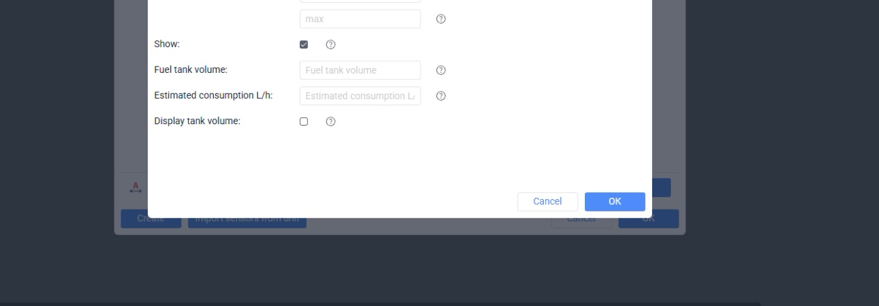
The Show option controls whether a sensor is visible to the customer.
Purpose
Sensor configuration gives meaning to raw tracker parameters and decides which values are visible, valid, converted, and reportable.
Where it affects the account
Sensors connect telemetry to monitoring cards, charts, fuel calculations, temperature traces, custom columns, and automation rules.
How to read the screen
For each sensor, confirm the parameter source, type, validation rule, conversion table, and whether the customer should see the value in daily work.
Screenshot 37. Show or hide sensor values
Setup steps
1
Show values that operators should act on.
2
Hide intermediate sensors used only for calculations.
3
Use clear names for every visible value.
4
Check customer UI after changing visibility.
Focus detail. Show or hide sensor values
Administrator note
Too many visible sensor values make monitoring harder to use.
Result
Show only values that the customer needs for daily work.
Check before continuing
Hidden does not mean unimportant; document internal sensors.
38Groups
Object groups
Object groups organize the fleet for monitoring, permissions, and support.
Purpose
Groups keep objects, commands, permissions, reports, and services manageable when a customer grows beyond one or two units.
Where it affects the account
A good grouping model reduces repeated permission changes and prevents accidental access to the wrong fleet or command set.
How to read the screen
Think in customer roles and operational teams, not in temporary installer convenience; the group structure should still make sense after expansion.
Screenshot 38. Object groups
Setup steps
1
Create group names that match customer structure.
2
Assign units immediately after creation.
3
Review groups before onboarding additional users.
4
Avoid duplicate groups with near-identical meaning.
Focus detail. Object groups
Administrator note
A good group model survives fleet growth.
Result
Groups are cheaper than cleanup.
Check before continuing
Do not postpone grouping until hundreds of units exist.
39Groups
Command groups
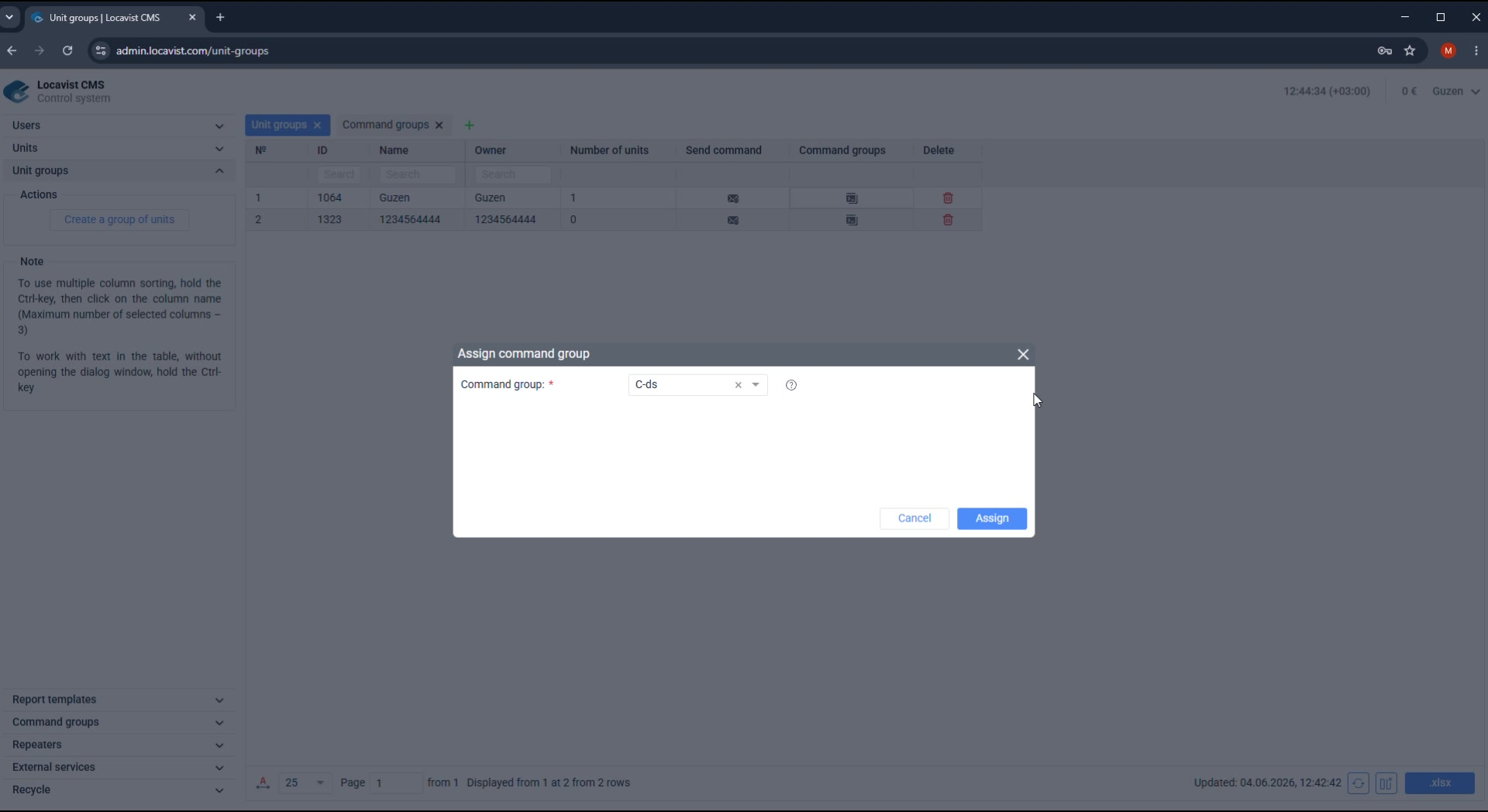
Command groups decide which remote actions users can run.
Purpose
Groups keep objects, commands, permissions, reports, and services manageable when a customer grows beyond one or two units.
Where it affects the account
A good grouping model reduces repeated permission changes and prevents accidental access to the wrong fleet or command set.
How to read the screen
Think in customer roles and operational teams, not in temporary installer convenience; the group structure should still make sense after expansion.
Screenshot 39. Command groups
Setup steps
1
Create command groups around roles, not around convenience.
2
Include only allowed commands.
3
Assign command groups to the correct users.
4
Test with a limited account.
Focus detail. Command groups
Administrator note
Remote command access is one of the most sensitive permission areas.
Result
Small command sets are easier to audit.
Check before continuing
Never give all commands when only one is needed.
40Reports
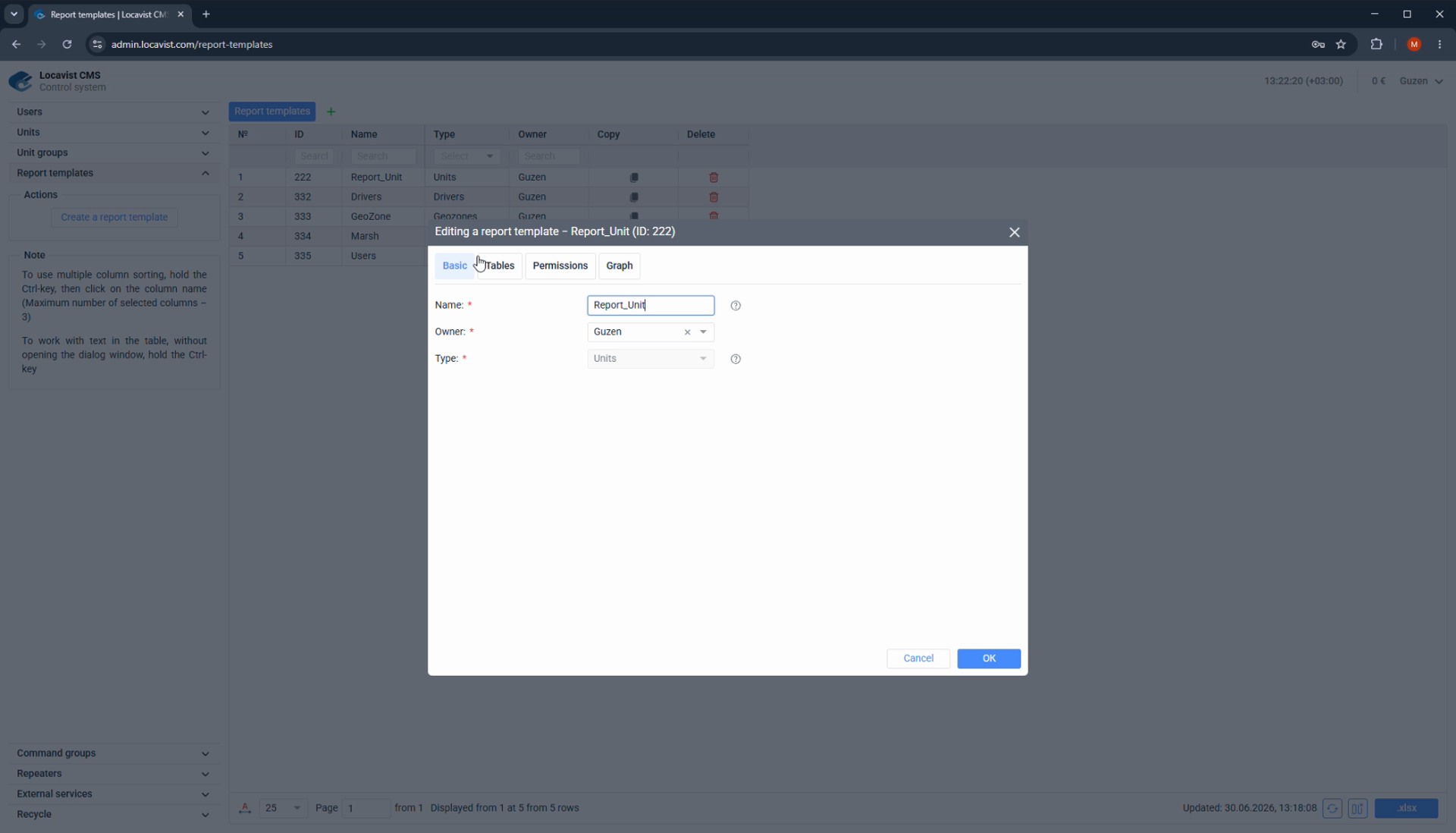
Standard reports before custom templates
Every new user already receives standard reports for mileage, engine hours, fuel, and common operational parameters.
Purpose
Report setup turns collected data into answers the customer can actually use for operations, finance, service, or compliance.
Where it affects the account
Report type, columns, intervals, graphs, and markers decide whether the customer sees a clear answer or a long table nobody trusts.
How to read the screen
Start from the business question, then choose the report type and columns; avoid building templates just because the controls are available.
Screenshot 40. Standard reports before custom templates
Setup steps
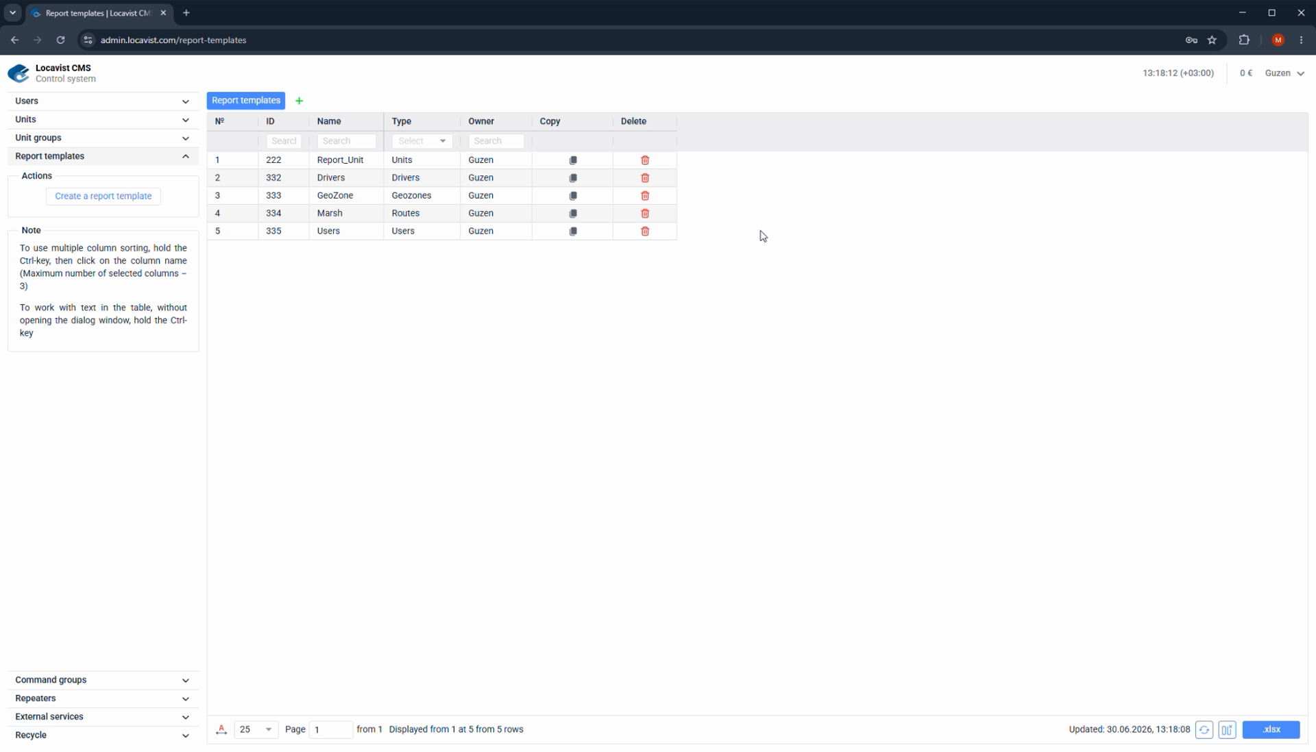
1
Open Report templates in CMS.
2
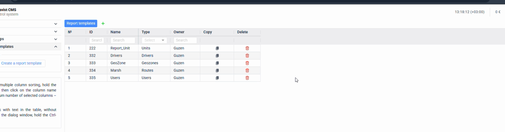
Review the table columns: Name, Type, Owner, Copy, and Delete.
3
Confirm whether the standard set already answers the customer's request.
4
Create a custom template only when the customer needs a focused report with no extra data.
Focus detail. Standard reports before custom templates
Administrator note
The reports video adds a useful rule: custom reporting should start from a real user need, not from duplicating everything the platform already provides.
Result
Standard reports keep onboarding faster.
Check before continuing
Do not create a custom template just because the Reports tab is available; an empty table can simply mean the current account has no templates yet.
41Reports
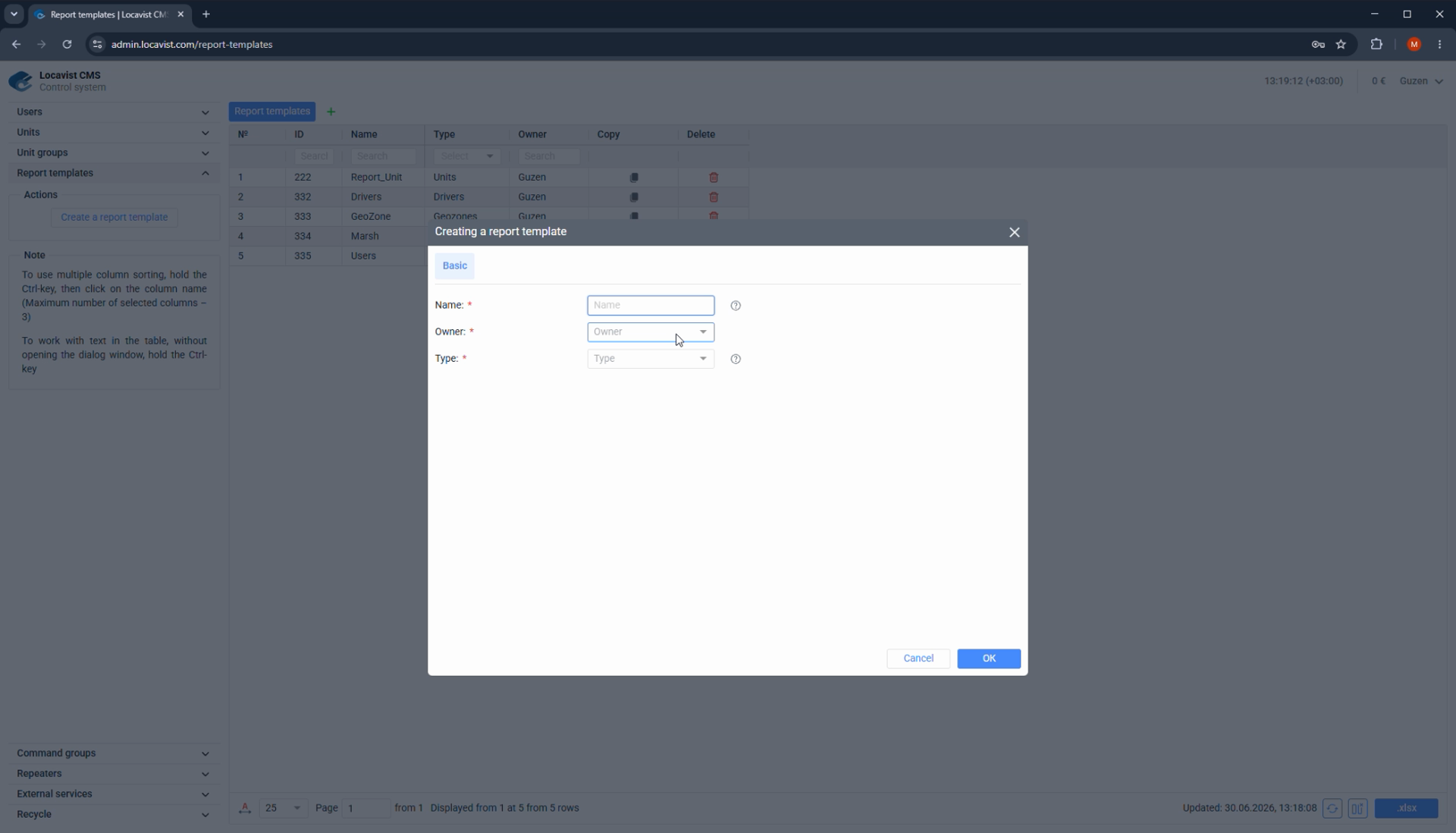
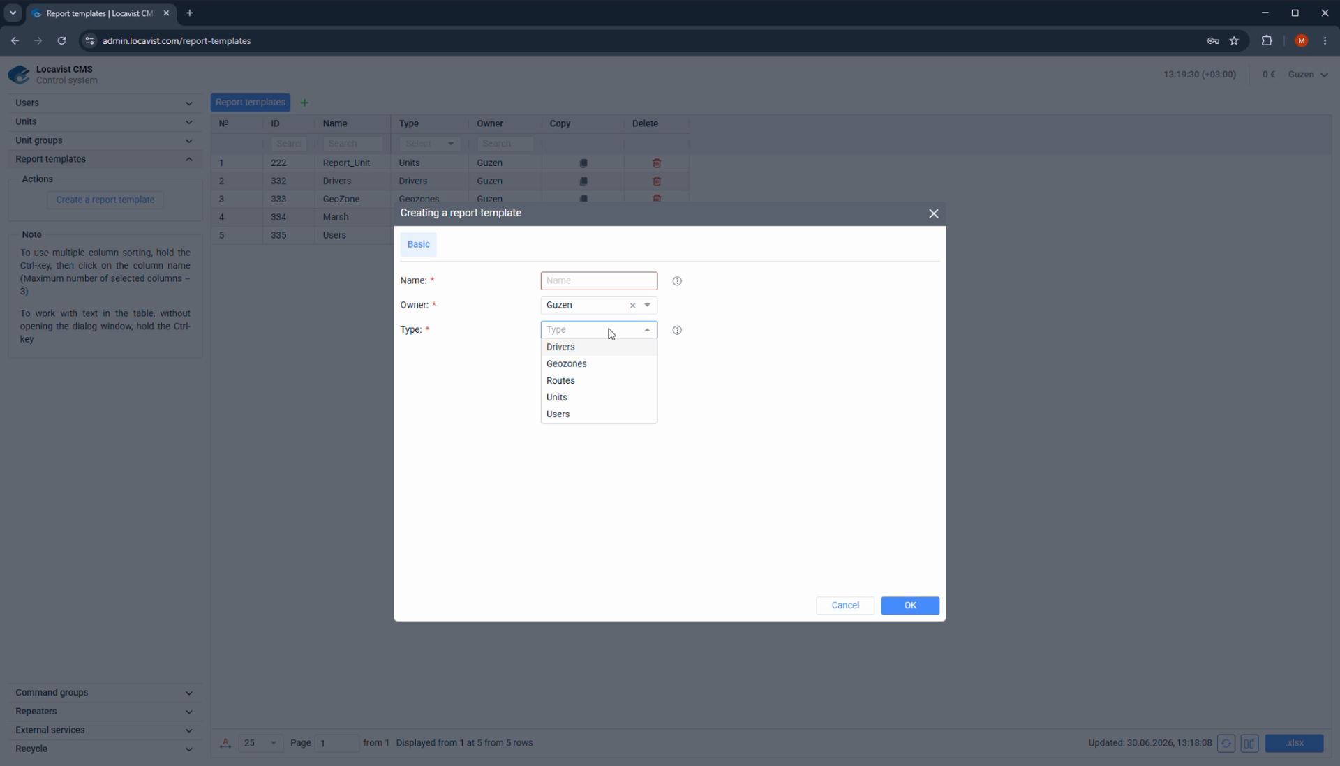
Create a report template
A custom report template belongs to a specific owner and starts with a report type.
Purpose
Report setup turns collected data into answers the customer can actually use for operations, finance, service, or compliance.
Where it affects the account
Report type, columns, intervals, graphs, and markers decide whether the customer sees a clear answer or a long table nobody trusts.
How to read the screen
Start from the business question, then choose the report type and columns; avoid building templates just because the controls are available.
Screenshot 41. Create a report template
Setup steps
1
Click Create a report template.
2
Set the owner: the user account that will receive and use the report.
3
Choose the report type before adding tables, columns, or graphs.
4
Name the template in a way support can recognize later.
Focus detail. Create a report template
Administrator note
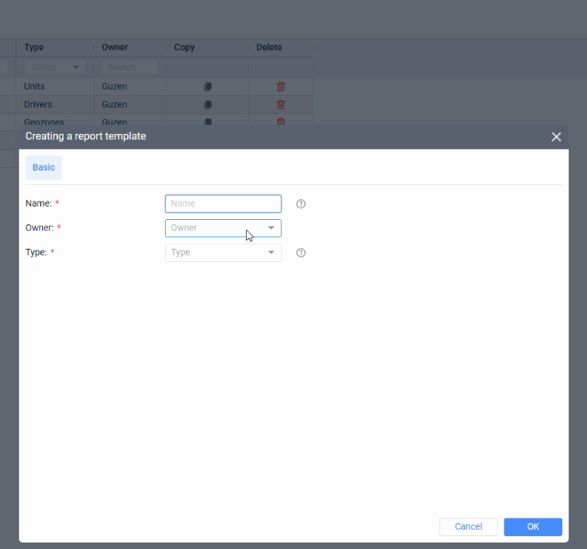
Owner selection decides where the report appears and who can work with it. Type selection defines the rest of the configuration path.
Result
Reports should be owned deliberately.
Check before continuing
A template attached to the wrong owner looks like missing functionality to the customer.
42Reports
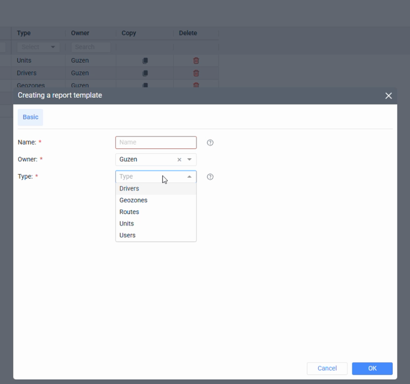
Choose the right report type
Report type should match the question the customer is trying to answer.
Purpose
Report setup turns collected data into answers the customer can actually use for operations, finance, service, or compliance.
Where it affects the account
Report type, columns, intervals, graphs, and markers decide whether the customer sees a clear answer or a long table nobody trusts.
How to read the screen
Start from the business question, then choose the report type and columns; avoid building templates just because the controls are available.
Screenshot 42. Choose the right report type
Setup steps
1
Use Driver reports for driver profiles and assignments to objects.
2
Use Geozone reports to see visits, time inside zones, distance, parking, and fuel behavior in zones.
3
Use Route reports when a user has routes and needs schedule or checkpoint compliance.
4
Use User reports to audit user actions and IP addresses.
5
Use Unit reports for broad vehicle statistics and operational detail.
Focus detail. Choose the right report type
Administrator note
Choosing the type first prevents a confusing template where the customer gets the right columns inside the wrong report logic.
Result
Type is the report's operating model.
Check before continuing
Do not use a Unit report as a universal workaround when the request is really about drivers, geozones, routes, or security audit.
43Reports
Unit reports and statistics
Unit reports are the broadest report category and can summarize vehicle activity for a selected interval.
Purpose
Report setup turns collected data into answers the customer can actually use for operations, finance, service, or compliance.
Where it affects the account
Report type, columns, intervals, graphs, and markers decide whether the customer sees a clear answer or a long table nobody trusts.
How to read the screen
Start from the business question, then choose the report type and columns; avoid building templates just because the controls are available.
Screenshot 43. Unit reports and statistics
Setup steps
1
Add a Statistics table when the customer needs a quick overview.
2
Include mileage, fuel consumption, idle time, stops, trips, and other summary fields only when they support the use case.
3
Use specialized tables for fuel dispensing, engine hours, digital sensors, or other detailed questions.
4
Keep the report readable by removing columns the customer will not use.
Focus detail. Unit reports and statistics
Administrator note
The reports video emphasizes that Unit reports can become very large. Useful templates are selective.
Result
Good reports answer one workflow clearly.
Check before continuing
Too many active tables make the report harder to trust and explain.
44Reports
Sensor trace reports
Some customers need a report that lists a specific sensor or parameter value across the whole interval.
Purpose
Report setup turns collected data into answers the customer can actually use for operations, finance, service, or compliance.
Where it affects the account
Report type, columns, intervals, graphs, and markers decide whether the customer sees a clear answer or a long table nobody trusts.
How to read the screen
Start from the business question, then choose the report type and columns; avoid building templates just because the controls are available.
Screenshot 44. Sensor trace reports
Setup steps
1
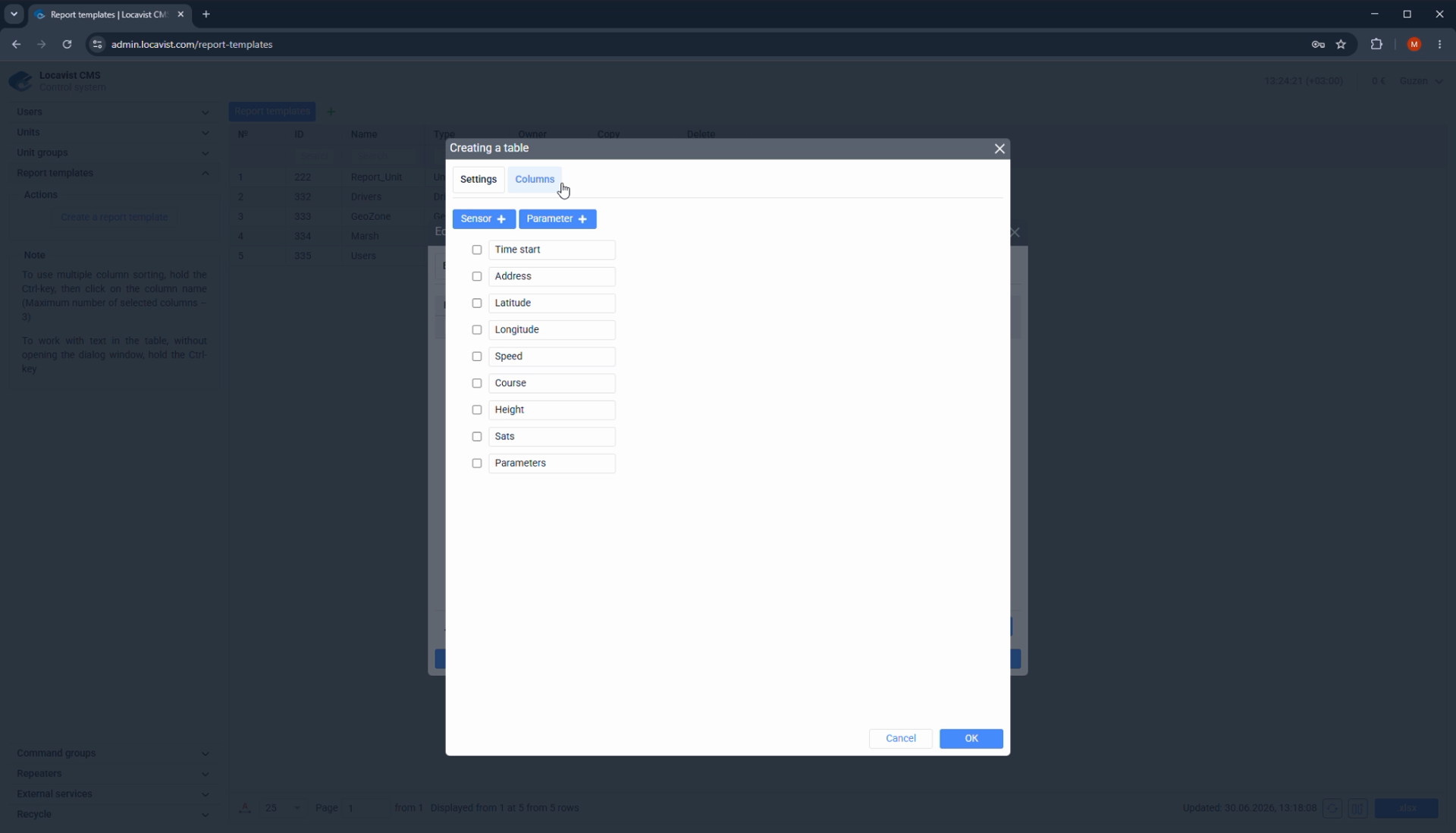
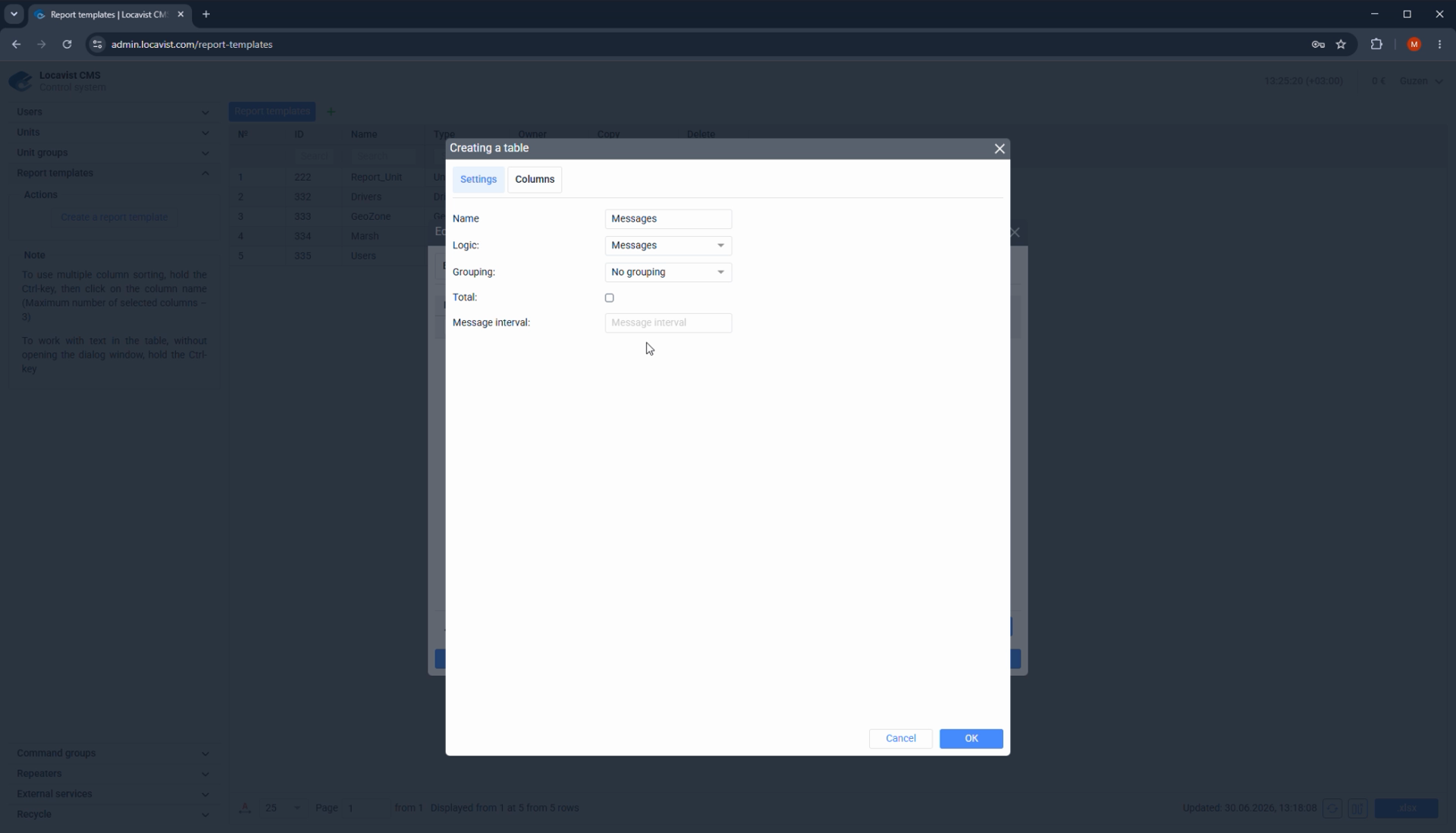
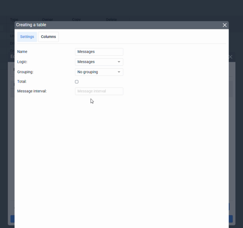
Use Messages logic when every incoming message matters.
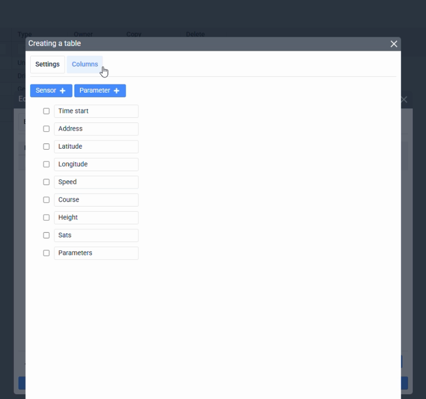
2
Open Columns and add Sensor.
3
Enter the sensor name exactly as it is named on the object.
4
Add supporting columns such as address, start time, and speed.
5
Reorder columns so the report reads naturally.
Focus detail. Sensor trace reports
Administrator note
The refrigerator example from the video is a good pattern: the customer needs a temperature trace for the whole trip, so the sensor column becomes the main payload.
Result
Exact sensor naming matters.
Check before continuing
A one-character mismatch can make the report look empty or incomplete.
45Reports
Message interval sampling
Message interval reduces dense message-level reports to a regular sampling step, such as every five minutes.
Purpose
Report setup turns collected data into answers the customer can actually use for operations, finance, service, or compliance.
Where it affects the account
Report type, columns, intervals, graphs, and markers decide whether the customer sees a clear answer or a long table nobody trusts.
How to read the screen
Start from the business question, then choose the report type and columns; avoid building templates just because the controls are available.
Screenshot 45. Message interval sampling
Setup steps
1
Ask whether the customer needs every message or a regular interval.
2
Set Message interval when the report should sample values periodically.
3
Use five minutes only when it matches the task; choose another interval when needed.
4
Explain that interval reports trade detail for readability.
Focus detail. Message interval sampling
Administrator note
The same temperature report can be useful at message level or at a five-minute interval. The right choice depends on what the customer will do with the data.
Result
Sampling makes long reports easier to read.
Check before continuing
Do not reduce interval detail when the customer needs evidence for every point.
46Reports
Graphs and event markers
Graphs can show standard parameters, sensors, and event markers above the chart.
Purpose
Report setup turns collected data into answers the customer can actually use for operations, finance, service, or compliance.
Where it affects the account
Report type, columns, intervals, graphs, and markers decide whether the customer sees a clear answer or a long table nobody trusts.
How to read the screen
Start from the business question, then choose the report type and columns; avoid building templates just because the controls are available.
Screenshot 46. Graphs and event markers
Setup steps
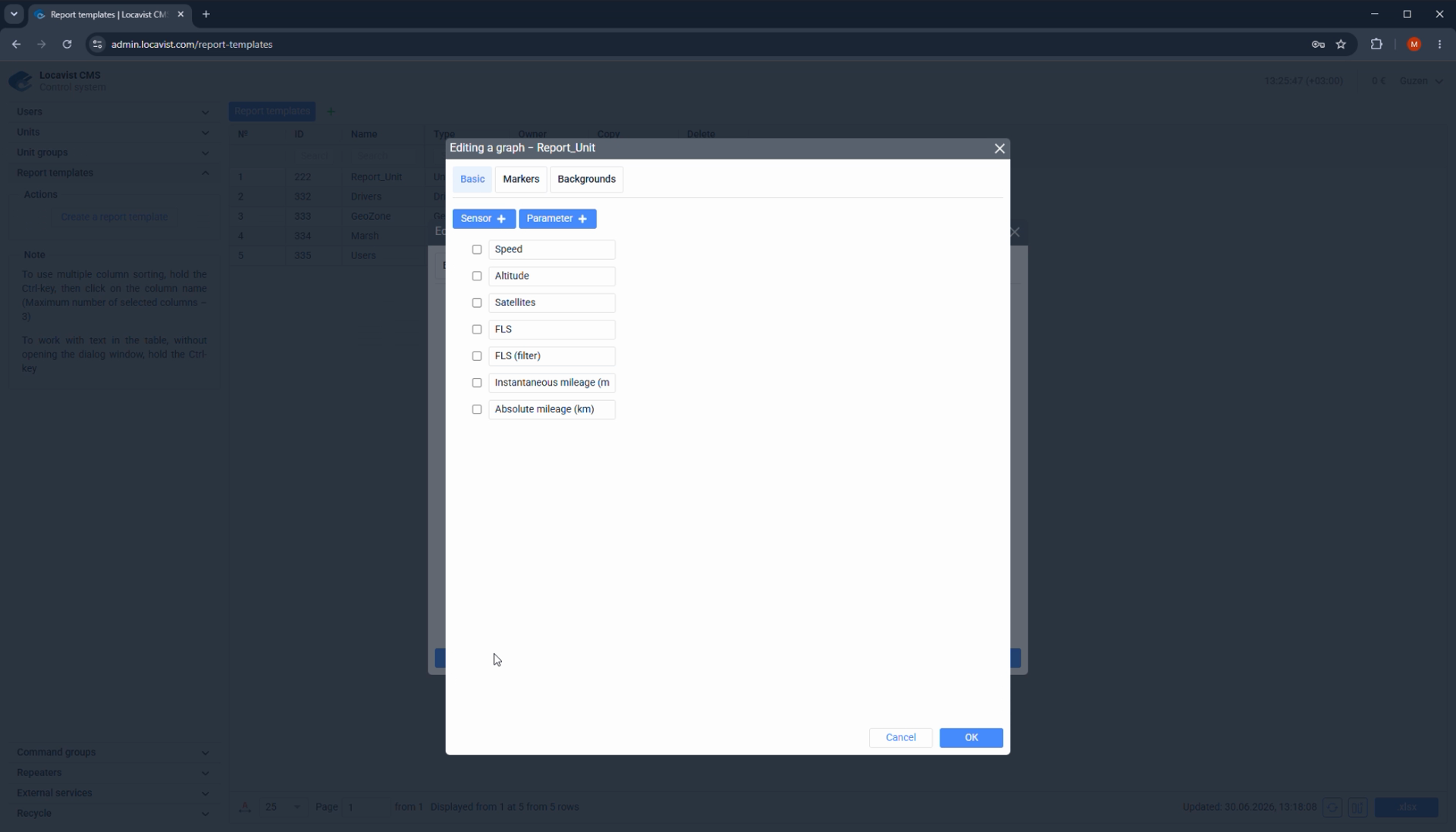
1
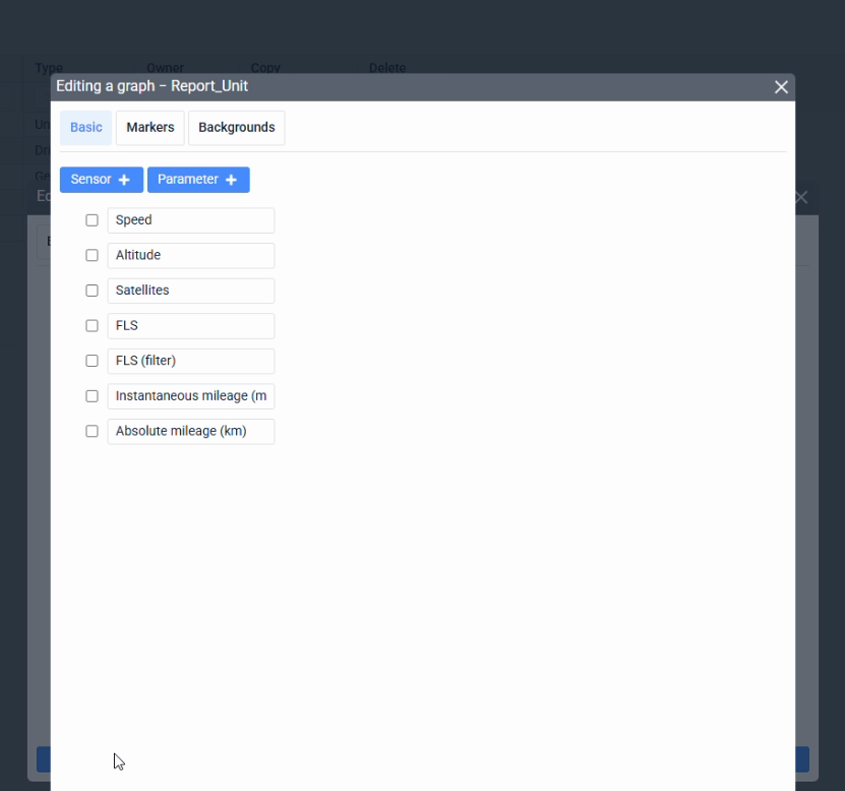
Add standard graph parameters such as speed, altitude, satellites, fuel, filtered fuel, or mileage.
2
Add specific sensors or parameters when the customer needs them visually.
3
Enable markers for overspeeding, parking, refueling, stops, or fuel drains when they explain the chart.
4
Keep the graph focused on the operational question.
Focus detail. Graphs and event markers
Administrator note
Graphs are strongest when they combine a value trend with the events that explain why the value changed.
Result
Visual context speeds up investigation.
Check before continuing
Too many graph layers can hide the pattern the customer asked for.
47Reports
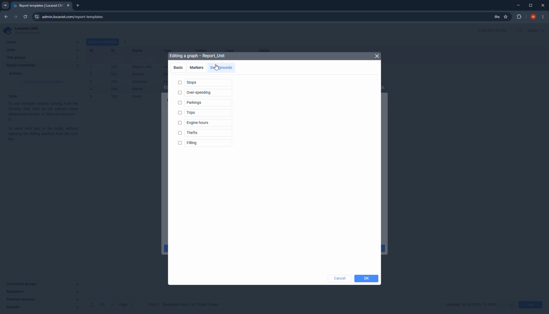
Graph backgrounds
Custom graph backgrounds add visual context for when an event or operating state occurred.
Purpose
Report setup turns collected data into answers the customer can actually use for operations, finance, service, or compliance.
Where it affects the account
Report type, columns, intervals, graphs, and markers decide whether the customer sees a clear answer or a long table nobody trusts.
How to read the screen
Start from the business question, then choose the report type and columns; avoid building templates just because the controls are available.
Screenshot 47. Graph backgrounds
Setup steps
1
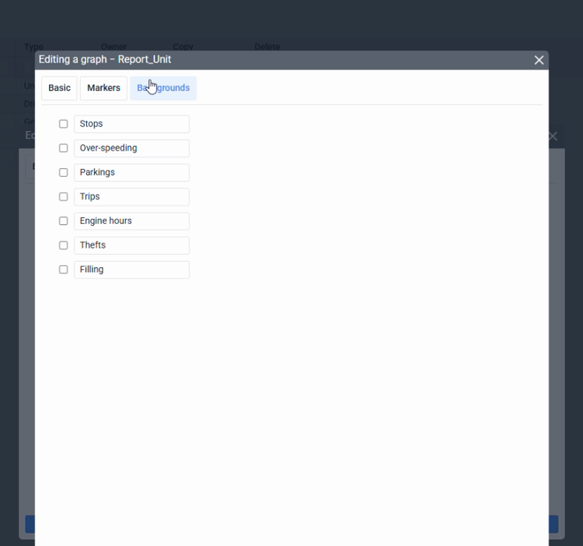
Open the Backgrounds tab for graph reports.
2
Choose backgrounds only when they clarify the timeline.
3
Use backgrounds to show operating states or important event windows.
4
Validate the final report with sample data before handing it to the customer.
Focus detail. Graph backgrounds
Administrator note
Backgrounds are useful when the report reader needs to see not only what changed, but what context was active at the same moment.
Result
Context turns charts into explanations.
Check before continuing
Do not decorate reports with backgrounds that do not help a decision.
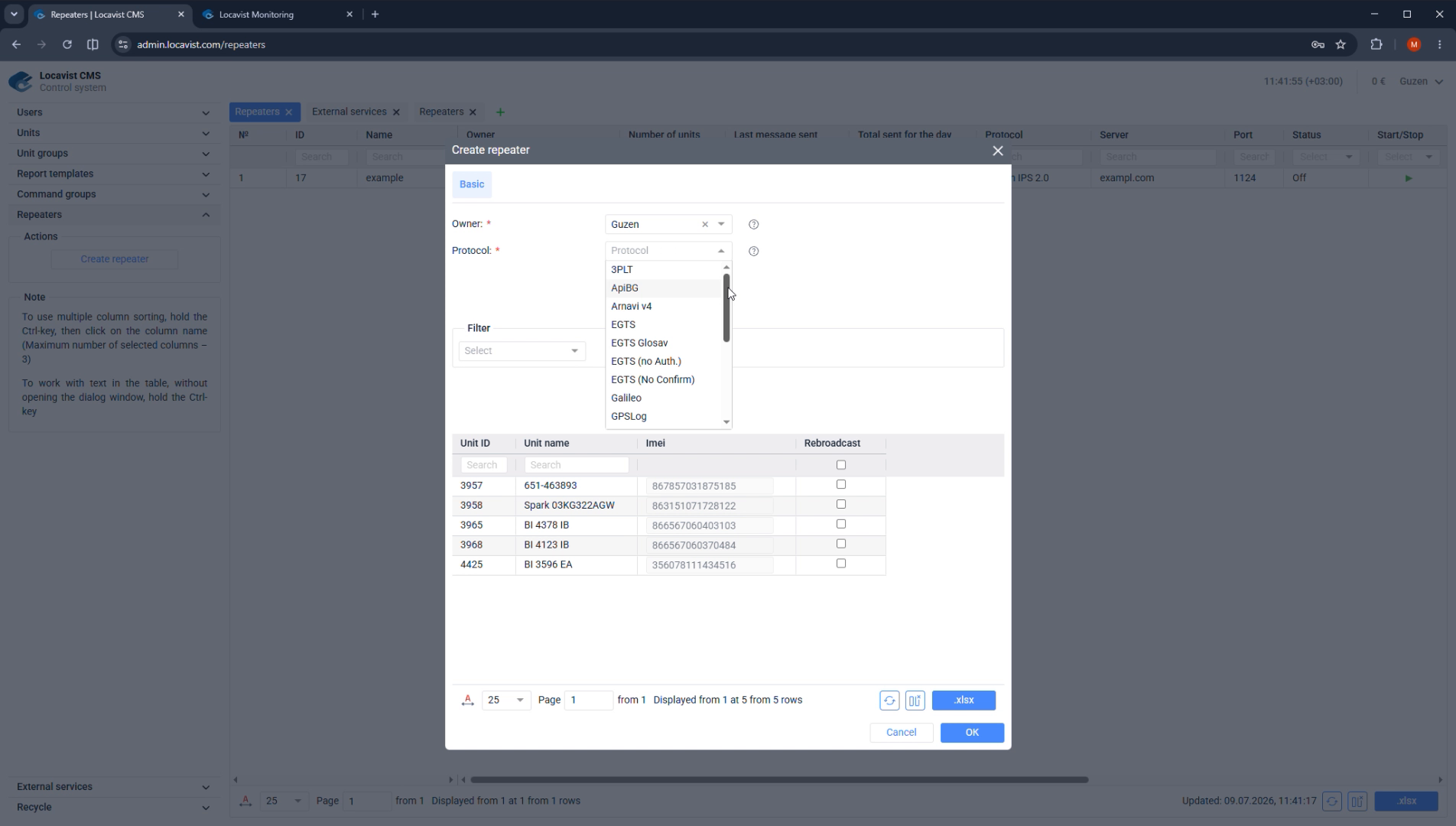
48Integrations
Create a data repeater
Repeaters forward Locavist messages to another monitoring system through a selected protocol.
Purpose
Integration pages describe data paths from Locavist to another system or service visible inside the customer workflow.
Where it affects the account
Repeaters, external services, statistics, and deletion behavior affect third-party data delivery, login flow, recovery, and accountability.
How to read the screen
Confirm the owner, destination, acknowledgement behavior, and customer-visible name before treating the integration as ready.
Screenshot 48. Create a data repeater
Setup steps
1
Open the Repeaters tab.
2
Select the owner, protocol, repeater name, destination server, and port.
3
Activate the repeater only after checking the destination details.
4
After saving, confirm that start, stop, server, port, and status are visible.
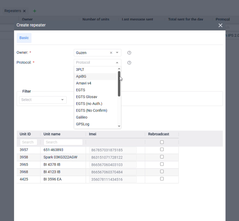
Focus detail. Create a data repeater
Administrator note
A repeater is not just a UI setting. It creates an operational data path from Locavist to another system, so ownership and destination details must be explicit.
Result
Clear repeater setup prevents silent data forwarding mistakes.
Check before continuing
Do not activate a repeater when the receiving server, protocol, or owner is uncertain.
49Integrations
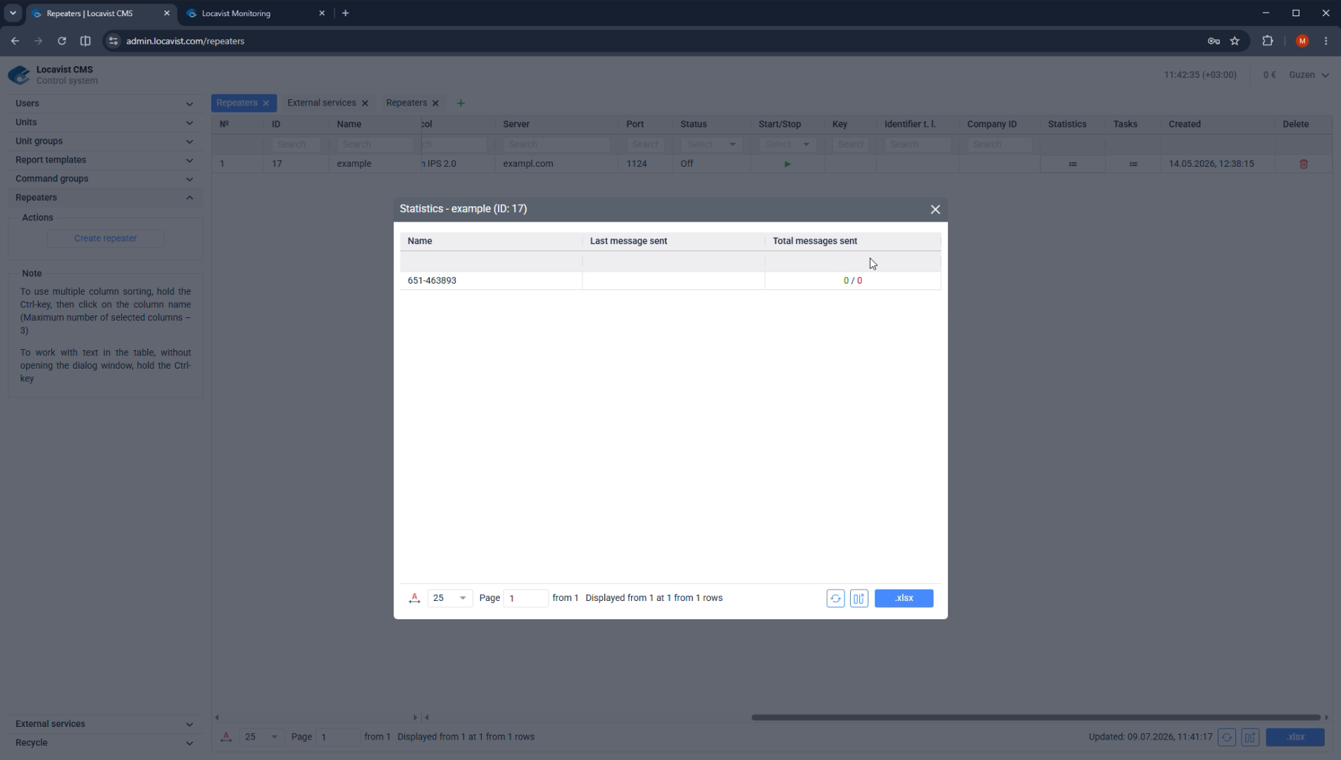
Repeater statistics and retransmission tasks
Repeater statistics show whether messages were confirmed, and tasks let you resend historical data to the selected retransmitter.
Purpose
Integration pages describe data paths from Locavist to another system or service visible inside the customer workflow.
Where it affects the account
Repeaters, external services, statistics, and deletion behavior affect third-party data delivery, login flow, recovery, and accountability.
How to read the screen
Confirm the owner, destination, acknowledgement behavior, and customer-visible name before treating the integration as ready.
Screenshot 49. Repeater statistics and retransmission tasks
Setup steps
1
Open daily repeater statistics and compare green and red message counts.
2
Treat green counts as sent and acknowledged packets.
3
Treat red counts as sent packets without acknowledgement from the receiving side.
4
Use Create task to select units and a time interval for retransmission when historical data must be sent again.
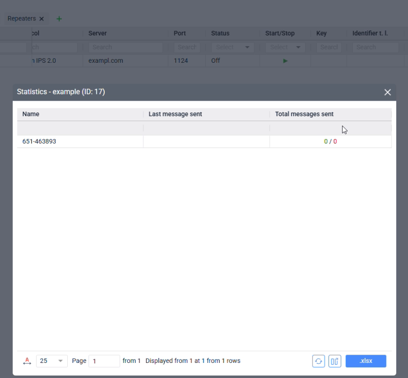
Focus detail. Repeater statistics and retransmission tasks
Administrator note
The red count does not automatically mean data never left Locavist. It means the receiving side did not acknowledge it, so troubleshooting should include the external system.
Result
Statistics separate delivery from acknowledgement.
Check before continuing
Do not promise that retransmission will create data that Locavist never received; it resends data available in the system for the selected interval.
50Integrations
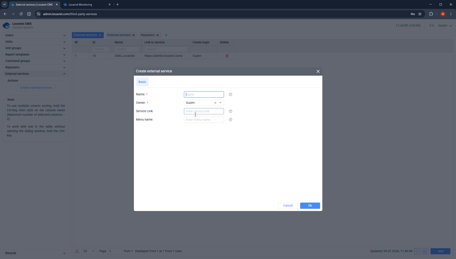
Configure an external service
External services add a third-party or integrator website to the customer's monitoring interface.
Purpose
Integration pages describe data paths from Locavist to another system or service visible inside the customer workflow.
Where it affects the account
Repeaters, external services, statistics, and deletion behavior affect third-party data delivery, login flow, recovery, and accountability.
How to read the screen
Confirm the owner, destination, acknowledgement behavior, and customer-visible name before treating the integration as ready.
Screenshot 50. Configure an external service
Setup steps
1
Open External services in CMS.
2
Review existing service rows by Name and Link to service.
3
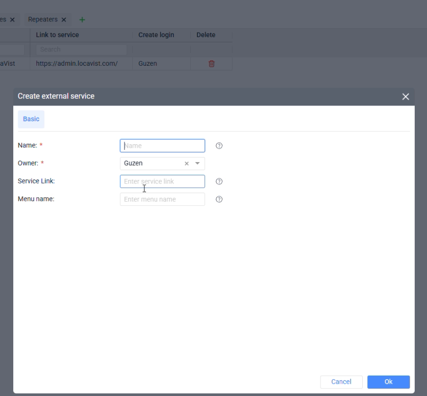
Use Create external service, then configure the service link and any login-creation behavior required by the customer's workflow.
4
After saving, use the Create login column only when the customer needs a generated service login.
Focus detail. Configure an external service
Administrator note
The live service list exposes Name, Link to service, Create login, and Delete columns, so verify both the URL and the login workflow before handover.
Result
External services keep customer workflow inside one familiar interface.
Check before continuing
Do not add an external service until permissions, the visible service name, and login behavior are clear to the customer.
51Integrations
Verify the service card in Monitoring
After an external service is saved, it should appear as a clear card or menu item in the user's monitoring workspace.
Purpose
Integration pages describe data paths from Locavist to another system or service visible inside the customer workflow.
Where it affects the account
Repeaters, external services, statistics, and deletion behavior affect third-party data delivery, login flow, recovery, and accountability.
How to read the screen
Confirm the owner, destination, acknowledgement behavior, and customer-visible name before treating the integration as ready.
Screenshot 51. Verify the service card in Monitoring
Setup steps
1
Log in to Monitoring with the intended user role.
2
Find the new service card using the name configured in CMS.
3
Open the card and confirm that it loads the intended website.
4
If the card is missing, recheck the service owner, visibility, and user permissions.
Focus detail. Verify the service card in Monitoring
Administrator note
The CMS form proves the service exists; the Monitoring check proves the customer can actually use it.
Result
Customer-role verification catches permission and naming mistakes.
Check before continuing
Do not finish setup based only on the CMS screen.
52Integrations
Recycle and permanent deletion
Recycle stores deleted items for recovery, but permanently deleting a user can also permanently remove that user's objects.
Purpose
Integration pages describe data paths from Locavist to another system or service visible inside the customer workflow.
Where it affects the account
Repeaters, external services, statistics, and deletion behavior affect third-party data delivery, login flow, recovery, and accountability.
How to read the screen
Confirm the owner, destination, acknowledgement behavior, and customer-visible name before treating the integration as ready.
Screenshot 52. Recycle and permanent deletion
Setup steps
1
Open the Recycle tab when an item was deleted and may need recovery.
2
Check Removed in and Days before removal to understand the recovery window.
3
Use Restore for items that must return to service; use Delete only after ownership and business impact are confirmed.
4
Before permanently deleting a user, confirm what should happen to all objects owned by that user.
Focus detail. Recycle and permanent deletion
Administrator note
Recycle is a recovery mechanism, not a safe parking place for live monitored objects. Deleted items show removal timing and stop behaving like normal live objects.
Result
Deletion behavior affects telemetry continuity.
Check before continuing
Do not permanently delete a user until ownership of important objects has been reviewed.
53Quality
Setup QA pass
Before handover, review the account as if you were the customer using it tomorrow.
Purpose
Quality checks prove the account works from the customer's point of view, not only from the administrator's CMS view.
Where it affects the account
This pass catches visibility, telemetry, trip, report, and permission problems before the customer discovers them during onboarding.
How to read the screen
Use a real customer role and a real unit wherever possible; mark any unchecked item explicitly instead of assuming it is harmless.
Screenshot 53. Setup QA pass
Setup steps
1
Log in with the intended user role.
2
Open monitoring and confirm the unit appears.
3
Check live data, trips, and sensor values.
4
Run one basic report if enough data exists.
5
Confirm hidden modules are intentionally hidden.
Administrator note
QA from the customer's point of view catches issues CMS screens do not reveal.
Result
Handover quality affects the customer experience from the first day.
Check before continuing
Do not hand over the account until it has been checked from the customer role.
54Handover
Client handover note
A short handover note keeps setup decisions visible after the installer moves on.
Purpose
Handover pages turn setup decisions into a supportable record after the installer leaves the project.
Where it affects the account
Clear notes preserve the billing model, access decisions, device identity, sensor logic, report choices, and known follow-up work.
How to read the screen
The account is ready only when the customer-facing workspace and the internal handover note tell the same story.
Screenshot 54. Client handover note
Setup steps
1
Record user role and billing model.
2
Record enabled and hidden modules.
3
Record unit ID, tracker model, and configured sensors.
4
Record known phase-two tasks.
5
Attach the first validation result.
Focus detail. Client handover note
Administrator note
The note becomes the record for setup, support, and future updates.
Result
Record setup decisions in the handover note so support can verify them later.
Check before continuing
Do not write passwords or sensitive tokens into handover notes.
55Handover
Operational checklist
Use this final checklist before telling the customer the account is ready.
Purpose
Handover pages turn setup decisions into a supportable record after the installer leaves the project.
Where it affects the account
Clear notes preserve the billing model, access decisions, device identity, sensor logic, report choices, and known follow-up work.
How to read the screen
The account is ready only when the customer-facing workspace and the internal handover note tell the same story.
Screenshot 55. Operational checklist
Setup steps
1
User and role are correct.
2
Billing, balance, lock balance, prices, and limits are checked.
3
Menu and monitoring visibility match the contract.
4
First unit has correct name, owner, device ID, and model.
5
Tracker data is arriving.
6
Trip detector and first reports are validated.
7
Fuel settings and required sensors are validated.
8
Object groups, command groups, and permissions are checked.
9
Handover note is written.
Focus detail. Operational checklist
Administrator note
This page is the repeatable final check for the setup process.
Result
A checklist reduces missed steps during setup.
Check before continuing
If one item cannot be checked, handover should mention it explicitly.
56Handover
After handover support path
After the customer starts using Locavist, support should have a clear path for questions, corrections, and future changes.
Purpose
Handover pages turn setup decisions into a supportable record after the installer leaves the project.
Where it affects the account
Clear notes preserve the billing model, access decisions, device identity, sensor logic, report choices, and known follow-up work.
How to read the screen
The account is ready only when the customer-facing workspace and the internal handover note tell the same story.
Screenshot 56. After handover support path
Setup steps
1
Confirm who receives customer questions.
2
Keep the handover note available to support.
3
Log configuration changes with date, reason, and owner.
4
Recheck permissions after adding users or object groups.
5
Review the setup after the first real reporting cycle.
Administrator note
The same account will be touched by setup, support, and account management. Clear records prevent repeated investigation.
Result
Post-handover discipline keeps the customer experience stable.
Check before continuing
Do not make silent changes to billing, permissions, sensors, or command access.